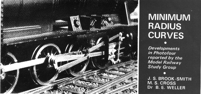
| MODEL RAILWAYS |
MARCH 1973 |
 The third article in this series describes a simple, rubber-controlled
fully-compensating suspension system for use with 6-wheel fixed-wheelbase carriage and
wagon stock. Protofour 6-wheel vehicles fitted with this system exhibit remarkably good
track holding characteristics and negotiate complex trackwork with ease, even at high
speeds. The longer wheelbase vehicles, if fitted with rigid suspension, are always likely
candidates for derailment and modellers may well find the new suspension an answer to
their problems. However, it is not necessarily the complete answer, for regardless of the
type of suspension employed, fixed-wheelbase vehicles are subject to the interaction of
certain other factors which influence trackholding ability. These are radius of curve, and
the associated factors of wheelbase, wheel incidence angle and sideplay.
The third article in this series describes a simple, rubber-controlled
fully-compensating suspension system for use with 6-wheel fixed-wheelbase carriage and
wagon stock. Protofour 6-wheel vehicles fitted with this system exhibit remarkably good
track holding characteristics and negotiate complex trackwork with ease, even at high
speeds. The longer wheelbase vehicles, if fitted with rigid suspension, are always likely
candidates for derailment and modellers may well find the new suspension an answer to
their problems. However, it is not necessarily the complete answer, for regardless of the
type of suspension employed, fixed-wheelbase vehicles are subject to the interaction of
certain other factors which influence trackholding ability. These are radius of curve, and
the associated factors of wheelbase, wheel incidence angle and sideplay.
Modellers are generally aware that the radii of model curves are often far smaller than
the minima found in the prototype, and that such radii restrict the operation of certain
types of stock. Why should this be so?
The wheels of fixed-wheelbase vehicles are aligned with the vehicle
centreline, and the rails are tangential to the curve of the track. There is thus an
angular displacement of the wheels and the rails whenever the vehicle stands on curved
track. The wheelbase is equivalent to the chord of a circle of which the track is the
circumference, therefore, for a particular radius of curve, the longer the wheelbase, the
greater the angular displacement between the wheels and the rails.
This characteristic applies equally to four-wheeled and six-wheeled stock, but in the
latter a sideways displacement of the centre wheel set may be necessary to enable the
vehicle to track round the curve.
From the foregoing it will be clear that wheel angle and side-play values are directly
related to the values of wheelbase and radius of curve. It is of interest to modellers to
know how these factors affect their stock and when they are likely to become limiting.
As the wheel angle to the rail increases, so do the frictional forces generated at the
wheel-to-rail contact points. Eventually a stage is reached at which a wheel will tend to
climb over the rail instead of running along it, and any further increase in angle,
however momentary, will cause derailment of the vehicle.
The determination of the actual point of contact between the wheel and the rail during
this process is a complex exercise, for the point moves from the rail head and wheel tread
down the curved surface of the flange. The friction generated is modified by many other
factors, such as the wear of the wheel and rail, wheel diameter, the speed of the vehicle,
the weight acting on the wheel, the centre of gravity of the vehicle, and its springing
characteristics. There are also effects of material texture and surface contamination, and
additional friction generated by contact with check rails, as anyone listening to
prototypical flange squeal can readily appreciate. As radii decrease and wheel angles
increase in proportion, wheel creep exerts a marked effect.
Wheel creep results from the disparity in length between the inner and outer rails of a
curve, and the consequent inconsistency between the ideal rotational speeds of the inner
and outer wheels, which of course are mounted rigidly on their axles. To some extent this
effect is countered by the coning of the wheel treads; for example, if the vehicle is
running with the outer wheels against the rail, the coning will give the outer wheels an
increased effective diameter compared to the inner wheels, and the former will therefore
run a greater distance for a given number of rotations. Unfortunately for the theory,
British Rail studies have shown that a four-wheeled vehicle tends to travel round a curve
with the front outer wheel flange in contact with the rail and with the rear pair in a
central position with respect to the rails. The result is that one or both wheels on each
axle will have a sliding as well as a rolling characteristic at the point of contact, with
a consequent increase in the frictional resistance. The above characteristics will also be
modified if the vehicle is pushed instead of pulled around the curve.
The nominal wheel angle may be calculated from the formula:
Sin (Wheel angle)= |
Wheelbase
2 x Radius of Curve |
- but in small radius curves the wheels will subtend at different
angles especially as the vehicle may be slewed across the increased gauge track. The
nominal sideplay may be calculated from the formula:
Sideplay (Versine)= |
(1/2 Wheelbase)2
2 x Radius of Curve |
- but here again the value must be corrected for clearance across
the track gauge. The radii used on the full-sized railways allow fixed-wheelbase vehicles
to be run around curves with little or no sideplay to the axles and well below limiting
wheel angles. However, the increased frictional forces generated by curved track appear in
the form of increased rolling resistance and increased flange wear. Six-wheeled carriages
were therefore given additional sideplay to the centre axleboxes, and the increased length
of the centre J-hangers allowed lateral travel to the springs. In locomotives the problems
were more acute. Deliberate thinning of the centre driving wheel flanges was common
practice; leading bogies with controlled sideplay tended to steer the leading drivers into
the curve; swivelling pony trucks and radial axle-boxes served much the same purpose. In
several cases, side-play in the leading driving axleboxes and flangeless driving wheels
were used.
Some or all of these measures could not prevent The Great Bear from derailing at No. 1
platform at Paddington, or the LNW 0-8-4Ts from straightening out the track below them,
but that is another story!
As with locomotives, attempts were made by Cleminson and others to reduce flange wear on
six-wheeled carriages by swivelling the end wheel sets in proportion to the sideplay. The
introduction of bogie stock no doubt owed as much to economic considerations as to
passenger comfort!
Where models are concerned, the economic and comfort factors are of little concern, and in
their place the technical problems resulting from minimal radii assume exaggerated
importance. It is therefore necessary to plan conservatively and to operate the layout and
its stock to figures below the critical values.
The only certain statement that can be made as to when wheel angles and sideplay become
limiting is when the vehicle derails!' and this must be established with particular
vehicles and track to the standard of the layout; however, MRSG studies with Protofour
stock suggest that wheel angles do not become critical below 3 deg. and in certain
conditions can be higher; 1mm is the average figure for sideplay available in scale
under-frames. A diagram showing the interaction of wheelbase and radius of curve, and the
consequent nominal values of wheel angle and (in the case of 6-wheel vehicles) sideplay,
is appended. From this graph readers may form some general idea of the relative
roadworthiness of particular vehicles.
The diagram shows that the minimum desirable radius, assuming the 3 deg. and 1mm figures
to be valid, for a 10ft 0in./40mm wheelbase van is 1ft 3 ins, while for the GW Passenger
Brake at 19ft0in./76 mm wheelbase, 2 ft 4 ins. On the other hand, a 6ft 0in. wheelbase
Airfix Pug fitted with 3ft 2ins equivalent dia. Protofour wheels has run many actual miles
around a 6in. radius curve at exhibitions, and this would suggest that for small diameter
wheels, 4.5 deg. is about the limit.
The wheel angle in locomotives is determined from the length of the
fixed wheelbase, but in certain cases, the effective wheelbase is the critical figure, For
example, the LSWR M7 0-4-4T has a nominal driving wheelbase of 7ft. 6in., but the
effective wheelbase is from the bogie pivot to the leading axle, i.e. 20ft. 5ins./81.7 mm.
In the same way, a Dean Single has the same effective wheelbase as the GW's 4700 Class
2-8-0's! Although wheel angle is a serious problem in model locomotives, it is usually
sideplay which offers the greatest difficulty. Six-wheeled carriages are now very rare,
but there is an increasing vogue for long-wheelbase four-wheeled express freight vehicles.
The BR CCT/GUV with 23ft. 6in./94 mm wheelbase is more critical in terms of wheel angle
than most locomotives. The use of Compensated Suspension units in long-wheelbase vehicles
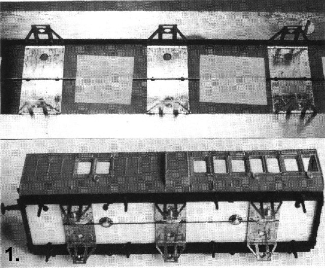
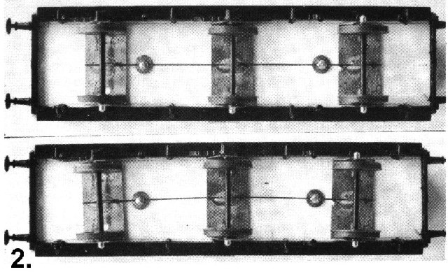
gives them a considerably enhanced performance. In six-wheeled vehicles, the units may be
used not only to follow track irregularities, but to cause the end wheel sets to swivel as
the centre axle displaces sideways. This is achieved by mounting the three suspension
units on a wire, which in turn is located in the slots of two 8BA screw heads set into the
vehicle floor inboard of the outer units. Sideways displacement of the centre unit on the
0.5 mm wire causes the screw heads to rotate, and so to give the end units a combined
slewing and rotating motion in the opposite direction. This characteristic enables
six-wheeled vehicles to be run safely around curves well below the nominal minimum radius.
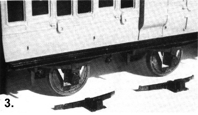
To stabilise the vehicle, the end units are given a narrow packing strip of Vilene
interlining felt, which allows them to slide across the underside of the floor. The centre
unit is suspended only by the wire, and so it can rotate on its torsion bar , and move
both horizontally and vertically to follow the configuration of the track. The
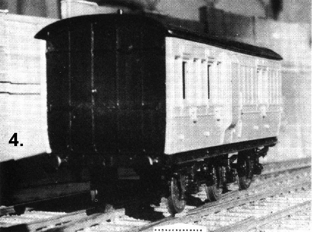
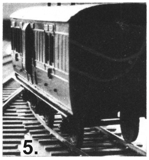
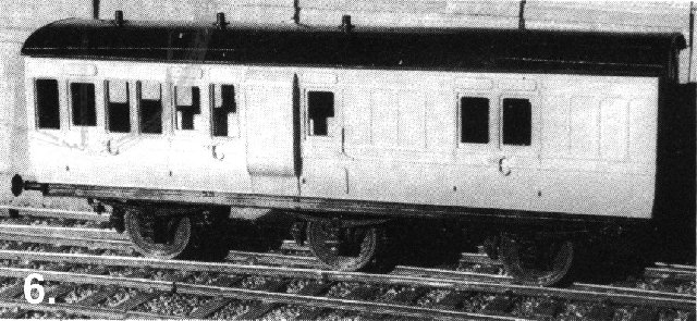
accompanying photographs show this system applied to a typical Ratio passenger vehicle;
given a certain amount of weighting, the riding of this vehicle is superb, and the body
remains completely stable.
The problem of small radii is central to 4 mm scale modelling. In
the past this problem has been approached by the use of overscale flange depth and tread
width, coupled with an under-scale back-to-back dimension, and as a result many other
compromises in scale dimensions are necessary.
Experiments with Protofour rolling stock show that such compromises are not necessary and
that by using the system described in this article 6-wheel vehicles can negotiate curves
of smaller radii than would be possible using BRMSB standards. Furthermore the quality of
running is vastly enhanced.
Nevertheless modellers have to accept that stock restrictions begin to appear at radii
below about 4ft. 0in. although their effects can usually be disguised. Below 3ft. 0in.
radius the restrictions become more obvious, and by 2ft. 6in. radius certain vehicles can
no longer be operated entirely satisfactorily.
On the other hand, the use of generous radii enables locomotives and other rolling stock
to be suspended in prototypical manner, and this has a remarkable effect on the stability
of the ride and the general level of performance. To the scale modeller, the advantages of
planning the layout to take advantage of the stock, as opposed to the other way round, are
obvious. Many modellers have sorely regretted the attempt to put a quart into a pint pot.
Copyright - Model Railway Study Group, reproduced with
permission.
Back to Magazine Index, Back to Site Index.
K Norgrove 25/04/03