| Model Railway Constructor | February 1967 |
| PROTOFOUR --- 2 a
new scale modelling standard J.Brook Smith, M.S.Cross, D.E.Jones, |
|
| Model Railway Constructor | February 1967 |
| PROTOFOUR --- 2 a
new scale modelling standard J.Brook Smith, M.S.Cross, D.E.Jones, |
|
Concerning Wheels
THE first article on Protofour gave brief details of the studies leading to its introduction. It will be recalled that in the tabulation of small scale railway modelling requirements, five cardinal rules were given for the attainment of reliable running. These were:
Both wheel and rail contours must be of the correct pattern for the standards used.
Wheel spacing on the axle (BB) must be correct.
Track Gauge (TG) must not be less than the nominal value and should include a gauge widening factor for curved track.
Check Gauge (CG) measured from the face of the check rail to the face of the outer running rail, must not be less than the nominal value.
Crossing Flangeway (CE) between the vee and the wing rails of a crossing, must be the specified value.
Of these five rules, the first is of great importance, as the balance of the remaining dimensions depends upon the contour of the wheel and the rail head with which it comes into contact. In this article it is proposed to examine wheel charactenstics in greater detail.
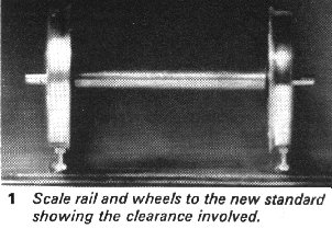
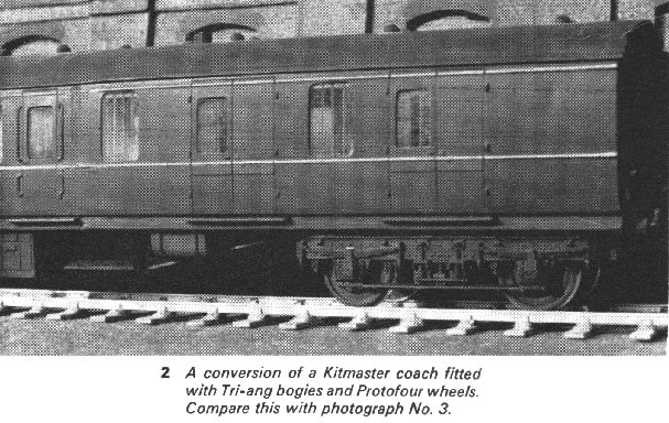
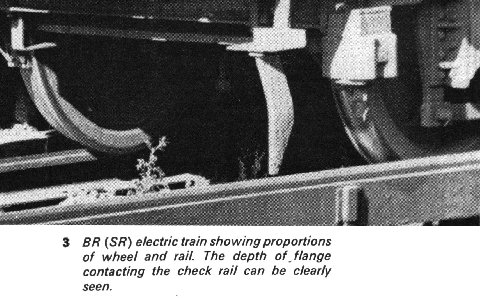
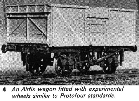
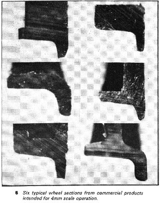
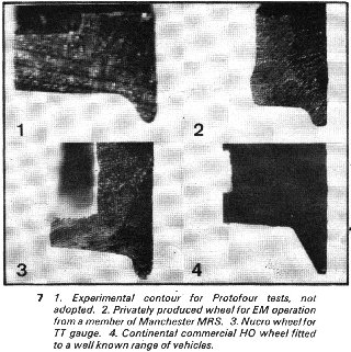
British Rail is currently running test vehicles fitted with a modified tread and flange contour which is claimed to give better riding and less wear than the standard contour, though it does not differ greatly from that used over the last century. It is interesting to note, too, that all prototype wheels, for standard or narrow gauge, have generally similar shape, size and flange contour. The British rail and wheel contours are laid down in the British Standard Specifications, to which all manufacturers must adhere. Unfortunately, in the model field there is no specification of the wheel and rail contours, apart from a few general dimensions. The result of this can be seen in the accompanying photographs of model wheel sections; as all of these are intended for 4mm scale operations, it requires little imagination to realise why model operations can be less than reliable on occasions.
To be able to design successful model wheels, it is necessary to discover the factors which affect wheel performance, and then to apply them. To find these factors it is necessary to examine the parts of the wheel and to determine their functions.
Wheel Tread
The wheel tread carries the weight of the vehicle, and is generally a flat surface. Except for the flangeless driving wheels of certain locomotives, the tread is coned at 1:20 and tapers into the flange. The coning is introduced to give a centreing tendency to the wheel pair, as any displacement from the neutral running position alters the effective diameters of the wheel pair so that there is tracking towards the neutral position once more. The rail is inclined at the same angle as the coning to give even wear of the rail and tread surfaces.
Flange and Flange Contour
The purpose of the wheel flange is to limit the sideways displacement of the wheel pair. This it does smoothly and effectively through a contour consisting of several radii, the most important one, between the tread and flange, matching the contour of the rail head.
If the face of the flange were vertical, as it becomes on some model wheels, there would be positive limiting of wheel displacement, but the flange face would "grind" the rail face on curves, and would foul any rail irregularities. The flange face must therefore be given a rake, which represents a compromise between trackholding and obstacle clearance requirements; in the prototype this rake is approximately 30deg but in the BRMSB wheel only 10 deg, though the latter is expected to negotiate sharper curves and greater irregularities of rail than ever appear in the prototype. The nose of the flange is radiused, giving it the optimum ability to accept track irregularities; again the model wheel recommended by the BRMSB is at variance with the prototype, being of a wedge shape.
|
|
|
| Flange Depth and Width The depth of the flange and its thickness are inter-related; these two dimensions are one of the most contentious issues in modelling. What is the minimum depth of flange? A visit to the Clapham Museum will confirm that "Mallard" ran steadily at 126mph on only 1-1/8in flanges: model authorities specify a flange three times this depth in equivalent terms. Unfortunately deep flanges mean wide flanges, and this sets a chain reaction through any table of dimensions. A wide flange needs a wider flangeway to provide proper running clearances, and a wide flangeway means even wider wheels to negotiate the crossings. It can be seen that the proverbial "steamroller" wheel of the model world is a direct result of excessive flange depth. |
|
| Nominal and Effective Flange Width The width of a flange is the distance between the back of the wheel and the point where the flange meets the tread, and its measurement should present no problem. However, the point where flange and tread meet is usually on a curved surface, and it becomes difficult to decide just where the flange ends and the tread begins. For the purpose of drawing up a table of dimensions, the nominal flange, based on wheel geometry, is less than satisfactory, and Effective Flange (EF) represents a far more practical value. Effective Flange is the distance between the running rail gauge face, and the back of the wheel, when the wheel is in a position of full deflection against the rail. Diagram 5 will show that the BRMSB wheel has an Effective Flange greater than the nominal value, when used with typical BRMSB rail sections. Thus, the Effective flange is greater than the value used in building the BRMSB Standards table, and this explains why erratic running can sometimes be found in certain BRMSB systems. It also brings the entire structure of BRMSB settings into question. |
|
From the foregoing, it is possible to determine the factors that produce a successful wheel. They are:
As all these features are found in the prototype wheel tyre contour, it is logical to adopt a scaled version of this contour for modelling purposes, which has been done in the Protofour standards. However, as the wheel tyre contour controls the remainder of the settings for track, it is advisable to examine certain other aspects of running before accepting this thesis.
Wheel Width
A viewpoint in model circles is that "narrow" wheels increase the incidence of derailments. Derailment owing to inadequate wheel width is possible in only two circumstances, namely; On plain track C where excessive gauge widening allows a wheel to fall between running rail faces. At crossings C where the wheel drops into the gap in front of the crossing nose.
The accompanying tables give an analysis of these situations.
Table 'A’ shows that on plain track, with the wheel pair fully deflected, the balance of dimensions is represented by TW + BB + EF versus TG.
Table 'B’ shows that at the nose of a crossing, a similar situation obtains, except that CF is added to TG.
Table 'C’ shows that the theoretical situation in 'B’ is modified in practice to give a balance represented by TW versus 2xCF.
Table 'D' shows that opposite the crossing the balance is represented by TW versus Check Flangeway, and is not critical.
In the prototype, the crossing flangeway is a fixed value in all conditions, and a spacing of 1¾in is maintained by bolting the rails together with spacing blocks, or fitting special chairs. The Check Flangeway, on the other hand, is a secondary dimension representing the difference between CG and TG at that particular location. As Table 'C' shows, Tyre width cannot be less than 2xCF, and the prototype wheel could therefore be as narrow as 3½in. Authority has prudently chosen a wheel 5in in tyre width, with locomotive tyres 5½in or more in width. For models, though, 2xCF is a minimum width, and if generous flangeways are the rule, an overscale wheel is the result.
Table 'E’ lists some settings used in modelling, and reveals certain critical situations. In '00’ Gauge, for example, the tolerance between wheel width and 2xCF is NIL (!) and '00' is supposed to be an easy scale to work to, on account of the wide flangeways; it is clear that unless the wing rails are perfectly aligned, there will be potential instability in running at the crossing nose. It is also clear that a tyre width of 2.5mm is mandatory for '00' operations, and American and Continental 'H0’ requires a tyre 2.7mm wide; in EM Gauge a 2.0mm wheel operates on the same reliability factor as '00'. As the prototype wheel is 5-5½in wide, the minimum width wheel in EM gauge is 10% overscale, in '00' it is more than 40% overscale, and in 'H0' 70% over-scale. This is the answer to those who claim that 'H0' is the ideal system for scale modelling. It has commercial potential owing to its wide acceptance, but is unsuitable for scale operations without modification of the wheel and track standards.
WHEEL TABLES |
E. |
00 | EM | EM2 | PROTO4 | PROTOTYPE EQUIV. |
|
EF | .75 | .75 | .75 | .40 | .38 |
| BB | 14.5 | 16.5 | 16.5 | 17.67 | 17.87 | |
| TW | 2.5 | 2.5 | 2.0 | 1.85 | 1.67 | |
| TOTAL | 17.75 | 19.75 | 19.25 | 19.92 | 19.92 | |
| TG | 16.5 | 18.0 | 18.0 | 18.83 | 18.83 | |
| * | 1.25 | 1.75 | 1.25 | 1.09 | 1.09 | |
|
EF+BB+TW | 17.75 | 19.75 | 19.25 | 19.92 | 19.92 |
| TG | 16.5 | 18.0 | 18.0 | 18,83 | 18.83 | |
| CF | 1.25 | 1.0 | 1.0 | .68 | .58 | |
| TG+CF | 17.75 | 19.0 | 19,0 | 19.51 | 19.41 | |
| * | NIL | .75 | .25 | .41 | .51 | |
|
TW | 2.5 | 2.5 | 2.0 | 1.85 | 1.67 |
| 2 x CF | 2.5 | 2.0 | 2.0 | 1.36 | 1.16 | |
| * | NIL | .5 | NIL | .49 | .51 | |
 |
TW | 2.5 | 2.5 | 2.0 | 1.85 | 1.67 |
| Check F | 1.25 | 1.0 | 1.0 | .78 | .58 | |
| * | 1.25 | 1.5 | 1.0 | 1.07 | 1.09 | |
| ALL DIMENSIONS IN MILLIMETRES | KEY:: TG: Track Gauge |
|||||
EF: Effective Flange, BB: Back to Back, TW: Tyre Width, CF: Crossing Flangeway |
||||||
Wheel Suspension
The "steamroller" wheels so beloved of our manufacturers are a result, as we have seen, of the insistence on deep flanges. The deep flange is considered essential to keep the vehicles on the tracks, owing to unevenness in the rail level. The prototype can also have some startling variations in rail level, which is why all prototype wheels are generously sprung. In modelling, for some obscure reason, it is almost impossible to find vehicles with adequately sprung suspension, though Peco, for instance, have made advances in this direction. This is a curious situation, as a simple spring arrangement is not a difficult matter, and a little downwards pressure on the wheel pair in an "Airfix" slotted axlebox would seem to be all that is required to remedy a source of constant trouble to modellers since models were first offered for sale back in Edwardian days.
Although pointed axles running in cupped bearings give the sweetest running to model wheels, it is rather difficult to incorporate pointed axles together with springing. For Prototour it has been decided to adopt a reduced diameter axle end, running in a slotted box, to allow the wheel to maintain constant contact with the rail.
Wheel Clearances
British rolling stock is almost always fitted with outside axleboxes, and the solebars or bogie frames are usually spaced to give 6ft. clearance between inside faces. As wheel pairs measure approximately 5ft 4½in over faces, there is 7½in, or 2.5mm in 4mm scale, in which to arrange the axleguards. If a standard setting between axleguard faces of 23mm is adopted, there is room for 0.5mm axleguards, and every variation of 4mm scale wheels, to be fitted to any vehicle.
Axles
Prototype axles measure approximately 5½in diameter which is equivalent to 15 SWG, or 0.072in. For comparison, Nucro axles measure 0.075in, or Stubs Steel Wire Gauge No. 48; Continental axles are 2.0mm (0.079in) diameter and Tri-ang axles are 14 SWG, or 0.080in diameter.
An ideal size for 4mm scale axles is therefore 15 SWG. If this diameter obtains for 22mm length, all 4mm wheel systems can be accommodated within the 23mm axleguard spacing. If the ends of the axles to 26mm overall are reduced in diameter to 1mm (or 0.040in approx) it is possible to accommodate the wheel pair in slotted axleboxes, with the capability of removal when necessary without damage to the vehicle. It would also be a simple matter to adapt these axles to pinpoint operation.
Conclusions
A wheel pair suitable for scale model railway operations should exhibit the following characteristics:
|
No commercially produced wheels exhibit all these
desirable characteristics, and the impression gained is that much of the difficulty facing
the modeller today is a result of poor wheel design and inadequate production techniques.
It is poor design that necessitates deep and coarse flanges, wide flangeways and ever
wider wheels. Because wheels in general have been so marginal in performance; a failure of
the BRMSB/ META organisation either to develop or standardise its products; currency has
been given to the proposition that scale railway modelling is impracticable, "you
cannot scale nature". In some circumstances nature, and manufacturing tolerances, can
be limiting factors, but there is no reason why correctly scaled wheels should not be used
with 4mm scale models, provided that the track and wheel components are properly designed
and produced under controlled conditions. These essentials are a feature of the Protofour system, and while the discoveries of evidence of inadequate design in contemporary products may cause discomfort in some quarters, it will be seen that Protofour is indeed a complete breakaway from past practice. The Study Group hopes that the new standards will enable modellers to produce scale model railways to a realism previously considered impossible of attainment, with comparative ease and a sense of real achievement. Only the appearance of accurate, reliable and convincing model railways will change the public view of the present hobby as an extension of the nursery floor; Protofour offers the key to the adult enjoyment of modelling the world's most fascinating transportation medium. |
|
Copyright - Model Railway Study Group, reproduced with permission.
Back to Magazine Index, Back to Site Index.