| Model Railway Constructor | June 1967 |
PROTOFOUR --- 6 a new scale modelling standard by a model standards study group J.Brook Smith, M.S.Gross,
D.E.Jones |
|
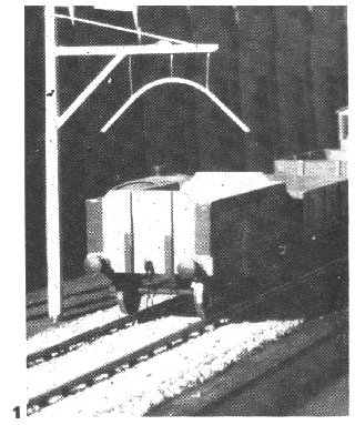
| Tracklaying | 1 An example of Protofour track |
| Model Railway Constructor | June 1967 |
PROTOFOUR --- 6 a new scale modelling standard by a model standards study group J.Brook Smith, M.S.Gross,
D.E.Jones |
|
| Tracklaying | 1 An example of Protofour track |
IT has taken us rather a long time to reach the stage of tracklaying, but perhaps the journey has been worthwhile, if only to marshall the facts of model railway track in some kind of order.
We began by producing a new set of standards, and explained what made certain wheels suitable or unsuitable for model railway operations; limitations of six-wheeled vehicles on model curves were discussed; Part Four introduced the Protofour components and stressed the importance of proportions, colour and texture in track components; Part Five brought us to the stage of tracklaying through the construction of track in a jig. We make no apology for once again stressing the three-dimensional aspect of track, and for pointing out that track alignment and rail level is dependent upon a level baseboard. Chiphoard is recommended as a suitable baseboard material because of the minimum tendency to warping and its reasonable dimensional stability, also because it is really flat - it is manufactured that way. Cork sheet, fairly thin, perhaps 2mm, makes the best underlay, and PVA adhesive the best bond for both underlay and track.
In the last article we prepared the track sections, and drafted out the track layout on the underlay, and then stuck the underlay to the bases. It is advisable to place flat weights on the underlay while it is setting, and in any case the underlay should be located by drawing pins at intervals.
For those adventurous souls who wish to incorporate superelevation on the curves, the need for caution was stressed, and adequate adhesive where the underlay rises from the base to the superelevation strip. When the underlay is firmly bonded, the edges are trimmed to give a correct contour to the ballast layer, and the whole area brushed off ready for tracklaying itself.
Prior to bonding, the track was tailored in position on the underlay, and we did not mention at the time how the rail should be cut off and trimmed. This is accomplished by the use of a pair of cutters, made from standard end cutters, which have been ground down to give a single bevel cut in place of the twin bevel which is standard on these tools. This single bevel gives a very neat edge to the rail, and does not flatten or distort it in the way that a twin bevel cut tends to do. Nonetheless, a fine file should be used to produce an absolutely flat end to the rail wherever there is a break.
|
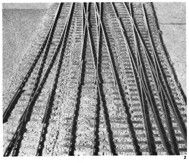
2 Some complicated pointwork in Protofour but laid in exactly the way as described in the accompanying text. |
Following our advice on the subject of colour and texture, we now proceed to weather the sections of track. As noted previously in the series, wooden sleepers were impregnated with creosote for protection, but creosote is an evil substance to have loose indoors, and it is far preferable to use paint to achieve the desired effect. We therefore use a large flat dish, or make up a flat tray using aluminium foil, in which to coat the sections of track with a very thin paint. The best description of the colour would be 'dirt' - matt colours, such as the 'Humbrol' range of earth, brown, stone, and mainly black, are ideal. This concoction is thinned with a very large proportion of turpentine or other solvent and brushed well into the sleepers. Indeed, the track sections may be immersed in the mixture. It should be noted that the paint is very thin indeed, as a darker shade can be given by means of a second coat, but a lighter one is not practicable. It is wise to experiment with spare sleepers until the required consistency is found, It is also wise to carry out these operations in the open, or at least out of the house, and in any case away from fire.
When the track has been washed with the mixture, it is laid on old newspapers to dry, and it will be noted that the grain of the wood is emphasised and a most lifelike effect obtained.
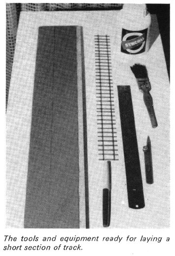
We are now ready for the tracklaying itself, and the adhesive, a felt-tip pen or other good marker, a steel rule, a brush for the adhesive, drawing pins, the ballast, and a supply of old newspapers are prepared. We commence by laying newspapers below the baseboard, partly to catch stray adhesive, hut mainly to collect the unused ballast for re-use. The edge line of the ballast is marked with the pen, and we are ready to start operations in earnest.
PVA adhesive has the golden advantage of being water-based, but resistant to water when set, which means that we may wash out our brushes without them becoming clogged or stiff, and a cup of water may be kept 'on site' to adjust the consistency of the adhesive or to wash out the brush as desired.
The underlay is covered with adhesive wherever the ballast is to be laid. For a first attempt, it is advisable to make up only a short section of track, perhaps for a showcase, until the procedure is understood. The adhesive must be of the correct depth and consistency, which means that it must be thick enough to coat the bottoms of the sleepers on contact, without being able to well over the sleeper tops when ballast is added: it must flow from the brush, without continuing to flow once it is on the underlay. It may be found of advantage to coat the underlay with water before applying the adhesive, and to add water judiciously from the cup during the operation.
Now comes the moment we have been waiting for - the track is lowered into position and held by a drawing pin at every fifth sleeper or so. The adhesive swath will give a good indication of the correct position of the track, but where double track or junctions are being laid, a card template with slots cut for the rails at correct spacing of the tracks may be of great assistance.
For the next few minutes we must work fairly efficiently, because the track has to be aligned closely to its final setting before the adhesive loses its fluidity, in which time we have also to apply the ballast. When the track is fairly well aligned, we take the packet of ballast and sprinkle it from a height of about a foot until the adhesive completely disappears, and then pack it gently down with the palm of the hand or with a brush. The surplus ballast is removed from the rail tops with the fingertip, so that the rail will be clearly visible for the final alignment.
The finest tracklaying tool in existence is the human eye, and one glance from it along the rail top will detect uneven track as surely as any instrument. Looking along the rail towards the light we will detect slight bends, waves and kinks, which may easily be checked against the straight edge of the steel rule. The rail can be slewed against the pull of the adhesive and drawing pins just as the full-sized permanent-way is slewed by gangers against the pull of the ballast, and care taken at this stage is amply repaid in the appearance and performance of the finished track, as we are adjusting the final axis of the three - alignment - and complementing gauge and rail level which were safeguarded in the jig and in the baseboard.
The adhesive will have taken half an hour or so to grip its layer of ballast firmly, and the baseboard may be upended over the newspaper to catch the surplus ballast for use on the next occasion. We do not wish to remove all the surplus ballast at this stage, but to clear the decks for small adjustments. Check, for example, that the rail ends are in alignment, and use the straight edge to confirm that the rail top is level and that the level is constant across rail joints. This is the last opportunity to make adjustments with ease, for in a matter of hours the track will be set firmly, and it will stay that way for the rest of its working life. Any further adjustments may still be made by soldering, so that the situation never gets out of control!
The bases are best left overnight to dry thoroughly, and on the next occasion they may be upended over a newspaper once again and given a thorough brushing to remove all surplus ballast. The drawing pins are removed, and the small areas spotted with adhesive and filled with the recovered ballast.
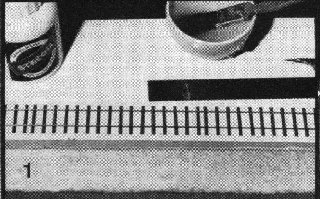
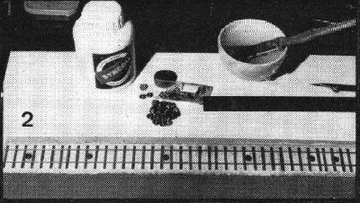
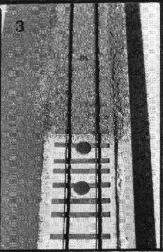
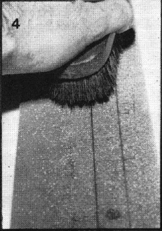
3 Laying operations. |
|
|
|
| (1) Swath of adhesive painted on to underlay to marked limits of ballast. | (2) Track set in position and pinned with drawing pins. |
| (3) Ballast sprinkled on to track and adhesive. | (4) Using a brush to pack ballast gently into adhesive. |
|
|
|
|
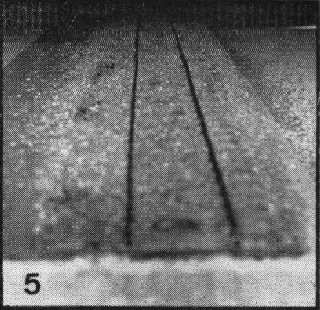
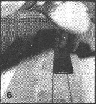
| (5) Railtops cleaned of ballast revealing slight misalignment. | (6) Using the straight-edge to align rails. |
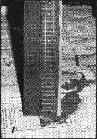
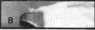
| (7) Collecting surplus ballast for re-use. | (8) Blockboard does warp This is why chipboard is recommended for baseboards. |
|
|
This series has been remarkable in that temperature expansion has hardly been mentioned. However, once the track ts firmly down, expansion and contraction come inexorably into play. If some relief is not given, the solder joints will eventually fatigue and break, and the merry ping of springing rail will be heard from time to time. Even where the solder joints do not part completely, severe strain is placed on the track and distortion of clearances and rail level is likely to occur. Therefore, just as in the prototype, expansion joints are necessary. A sixty-foot rail measures about 9½in in 4mm scale, and if the track is cut with a fine metal saw at this interval, or not more than approximately 1ft of unrelieved rail allowed, no trouble should be experienced. On the credit side, the operation gives the authentic wheel click, as only when the rail is completely cut does one hear the joint clicks clearly. The cut rail sections must be electrically bonded, but again this represents no real problem, as the rivet system is compatible with soldered connections.
The track is now ready for the addition of chair mouldings, which at the time of writing are still in the developmental stage. Kingsway chairs may be used if desired, and they should be snipped in half and added outside the rivet using a suitable adhesive, PVA, contact, or Araldite. The chairs are not necessary for the operation of the track and may be left off altogether if desired.
The final operation in bringing the track to life is to give the whole permanent way a wash of very thin dirt paint to harmonise the ballast and sleepering. Previously, the rail and chairs will have been given a coat of matt rust paint to lose the glint of metal, and this should discolour the ballast in the immediate vicinity of the rails. Special locations such as station stops need special treatment, where there is much rubbing of brake blocks and deposition of rust, and where steam and diesel locomotives leave ash and oil deposits respectively. Sidings do not have ballast in the same form as the running lines, and ash, or slag, is used instead. All these details, and others, will suggest themselves from personal observations, but it is wise to introduce effects carefully, so that no single characteristic becomes dominant.
This, then, is the basic tracklaying system of Protofour. It has been developed to offer the greatest possibility of satisfactory scale model running, by ensuring that preparation is based on sound principles, and that alteration and adjustment can be made at any stage of development. It is a reasonably simple system and it brings the construction of correctly scaled model railways within the ability of the average modeller. Now we can proceed to the most fascinating aspect of all- the construction of accurate switches, crossings and junctions, and the opportunity for the individual to reproduce or invent fascinating gems of railwayana in 4mm scale. |
 |
Copyright - Model Railway Study Group, reproduced with permission.
Back to Magazine Index, Back to Site Index.