|
|
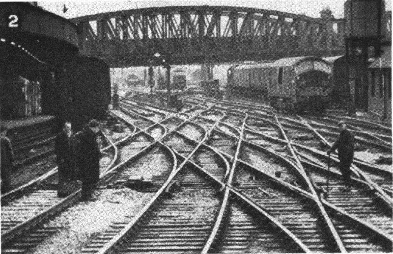
2 Paddington approaches, all single and double slips with identical crossing angles. |
|
|
|
| Model Railway Constructor | September 1967 |
PROTOFOUR --- 9 a new scale
modelling standard J. Brook Smith, M. S. Cross, D. E. Jones |
|
| switches, crossings and junction layouts. |
ONE of the main advantages of correctly proportioned scale standards is that all the track formations found in the prototype may be reproduced in model form without difficulty. Where the track gauge is distorted, as in compromise standards such as those of BRMSB, it is impossible to reproduce the correct six-foot way between tracks, owing to vehicle overhang and clearances. Similarly. the overscale flangeways cause difficulty in the construction of double slips, where several rails are set closely together. Protofour, being correctly proportioned, has none of these failings and trackwork, no matter how complicated, will always be authentic in appearance.
In this, the last of the present Protofour series, the construction of complex track-work will be discussed. However, such construction involves only extensions of techniques already described, and it seems appropriate that the basic dimensions of Protofour, and the basic trackmaking rules, should be stated again in a form convenient for reference. (See Box).
With these "Protofour Principles" in mind, it is necessary merely to describe the main features of prototype formations to enable construction to be carried out.
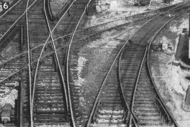
In previous articles we have noted how simple turnouts are constructed from two basic units: a pair of switches bifurcating the roads, and a common crossing where one running rail crosses its opposite number. Where this running rail continues on to cross a similar running rail in an adjacent road, the third of the triumvirate of basic units, the obtuse crossing, is used. These three units are combined in various ways to form every track layout on the railways. (Photo No. 6).
Diamond Crossings
The formation where two plain tracks cross is known as a "diamond", and is made from one pair each of common and obtuse crossings. Diamonds invariably have their timbering laid at right angles to the centre-line joining the common crossings and spaced symmetrically on either side of the centre timber placed below the noses of the obtuse crossings. As opposed to the common crossings, where timbering is spaced at standard 2ft 6in centres, obtuse crossings have timbering spaced according to the angle of the crossing; they are made in standard values from 1:4 to a maximum fineness of 1:8. Where the ratio of 1:8 is exceeded, the obtuse crossings must be replaced by pairs of foreshortened switches, and the resulting formation is termed a "switch diamond". These are worked and locked as turnouts, and are clearly more expensive to build and to maintain; they are usually found only at high speed junctions.
Model diamond crossing assembly commences with the accurate positioning of the common crossing vees, followed by the positioning of the cranked stock rail over the obtuse crossing centre timber. One end of the stock rail is then soldered to gauge opposite the common crossing and the steel rule laid against it and against the opposite common crossing nose. The nose of the obtuse crossing is then soldered into position using the steel rule to maintain alignment and gauge. This operation is then repeated for the remaining stock rail until the basic alignment and positioning of both common and obtuse crossings is attained.
The wing rails, which also form the point rails of the obtuse crossings, are next cut to size, and positioned so that the flangeways at both the wing rail end and the point rail end are correct. (The latter may be slightly wider than the nominal figure without affecting the running). Using the steel rule and a No. 71 drill or flangeway gauge, the wing rail is first tacked at the common crossing on the 'X' chair, and then at the point rail end. All the chairs are then soldered in turn. When all wing rails are secured, the check rails are added for both crossings. Note that the "Protofour Principle" regarding double check flangeways and nominal gauge is particularly applicable to diamond crossings.
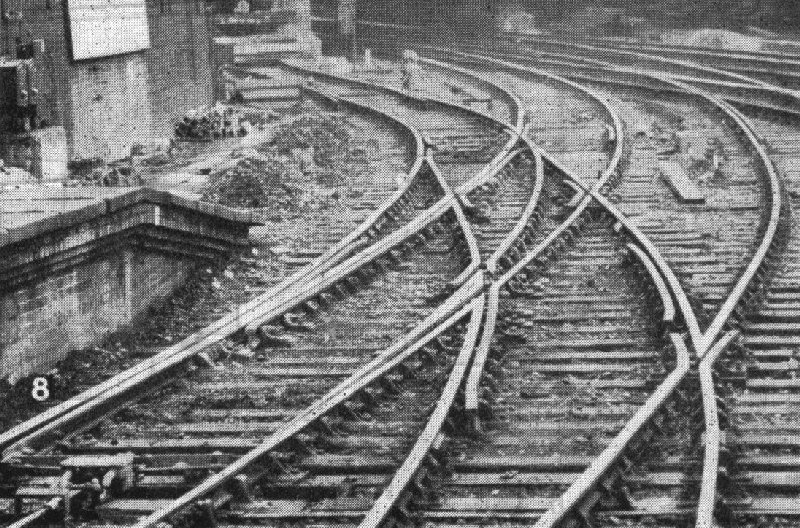
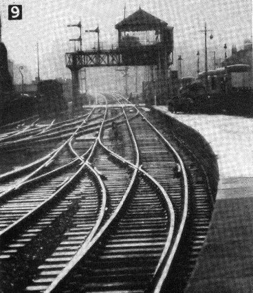
Crossovers. (Photo No. 9)
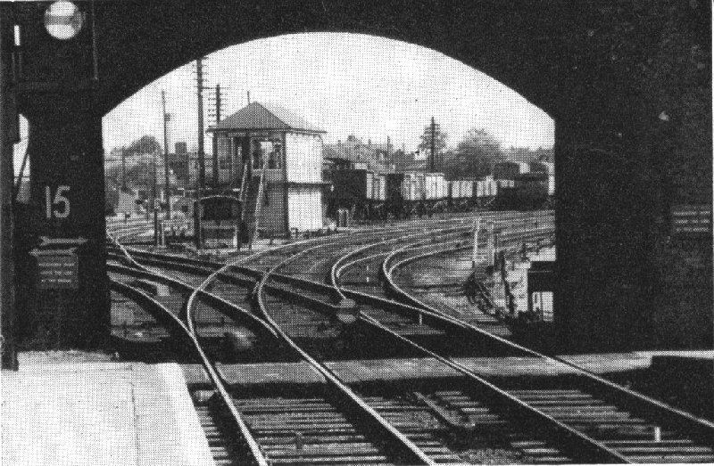
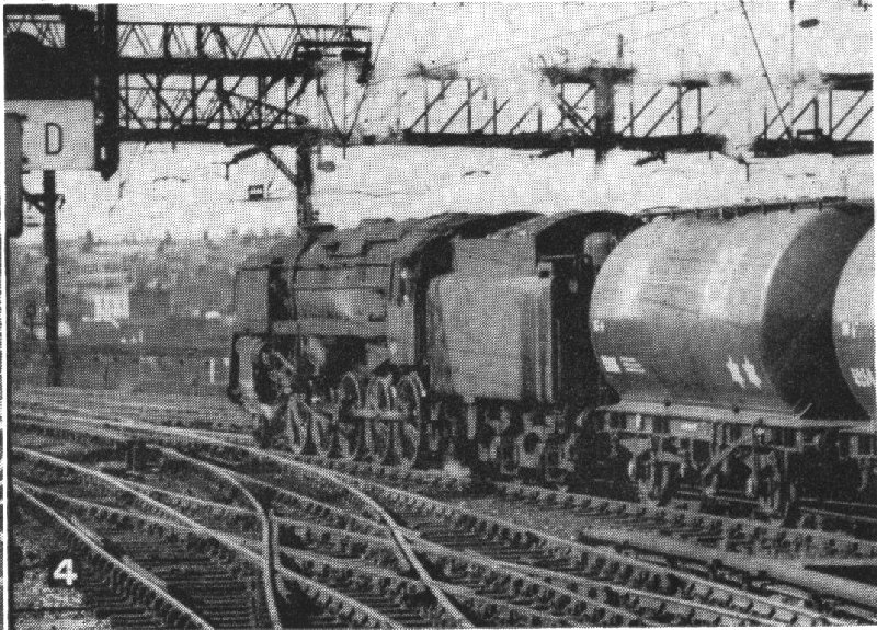
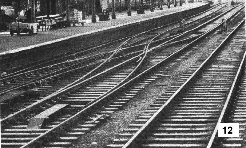
Two simple turnouts, one in each road of a pair of parallel tracks, may be placed so that the diverging roads form a "crossover road" from one track to the other. Where the crossover is set in a pair of main running lines it is generally trailing , so that the normal traffic flows through the switches from the heel to the toe. Where a crossover or turnout in such a situation is "facing", switch toe locks have to be provided and these have a characteristic cover. (Photos Nos. 1, 8 & 12). Occasionally, space considerations require crossovers for both directions at the same location, and these superimposed formations are termed scissors crossovers. (Photo No. 4). Pre-grouping station layouts often relied on these scissors crossovers, and Oxford remains to this day a typical example of their use. (Photo No. 12).
In crossovers, the timbering for the crossings is usually carried across both parallel tracks. There are two types of scissors diamond, one of which has all crossings at the same angle, and the other with common crossings forming part of the turnout curve. The latter are difficult to model. (Photo No.4).
Double Junctions. (Photo No. 1)
These consist of a pair of turnouts combined with a diamond crossing. Where the diamond has straight roads, both common and obtuse crossings will have the same value. However, where the diverging road curves through the diamond, the obtuse crossings will be of the same value but the common crossing angles will vary. The diamond crossing of a double junction therefore needs to be carefully drawn or calculated. One limiting factor in the design of a double junction will be the angle of the obtuse crossing, which cannot be finer than 1:8. On the other hand, a turnout crossing angle of 1:6 or less will cause excessive speed reduction through the junction. A good figure for a model junction would be 1:7, which would simplify choice and standardise production.
Normally both turnouts of a double junction have the same crossing angle and the inner turnout is set forward of the outer to provide a proper six-foot way through the junction. This advancement would be 3mm for a 1:7 turnout in 4mm/ft scale.
Quadrupled main lines often feature pairs of double junctions arranged as crossovers between fast and slow running lines; the Midland was very fond of them.
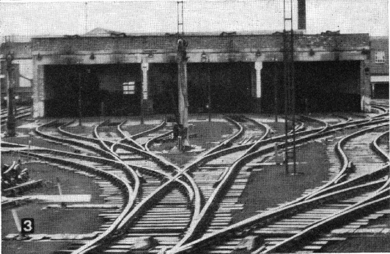
Interlaced or Tandem Turnouts. (Photo 3)
These are, as the name implies, two normal turnouts arranged so that the switches of the second turnout fall between the switches and the crossing of the first. The flexure of all three roads may vary, and so not only do these turnouts fit awkward locations easily, but they save considerable length, at the expense of one additional common crossing. They are still to be found in considerable numbers on British Railways, despite the wholesale lifting of sidings, and they are simple and efficient in model form. In designing tandem turnouts, the radii of the diverging roads must be so arranged that the additional common crossing does not lie too close to either running rail of the centre road, and the second pair of switches must be placed sufficiently to the rear of the first pair to allow full opening of the switch blades.
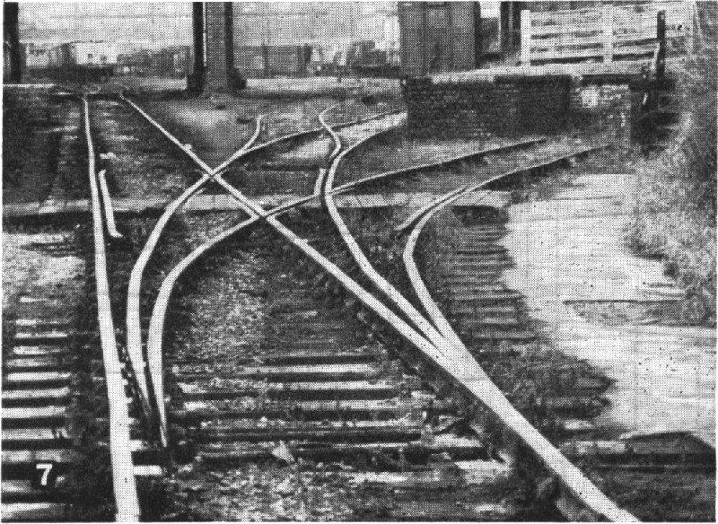
Three Throw Turnouts. (Photo No. 7)
These are similar to the tandem turnouts above except that the switches are combined instead of in separate pairs. The switch units are specially made and may have flatter planing than the equivalent plain switches. The switch blades for the outer roads are curious in that they are set one timber ahead of those for the inner roads, and this can give rise to gauging problems. For model purposes there is no reason why three throw switches should not be used, provided that the switches are carefully made and the turnouts used as on the prototype, only in sidings.
Single and Double Slips. (Photo No. 2)
These are plain diamond crossings in which two or four pairs of switches have been incorporated for the slip roads. The general order of construction is the same as for diamonds, except that the stock rails have to be set to gauge opposite the common crossings before the noses of the obtuse crossings can be positioned. The stock rails are first cut to size, curved by running them through the fingers under pressure, the sets marked 1 -1½ mm ahead of the switch toe and formed with the blunt nosed pliers, and the rail positioned and carefully tacked to gauge opposite the crossing. A single completed switch rail of adequate length is then positioned and marked at the point where it will form the nose of the obtuse crossing, and is cut approximately 3in longer than necessary to form the second switch.
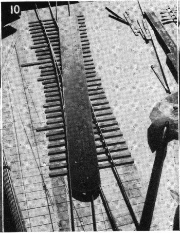
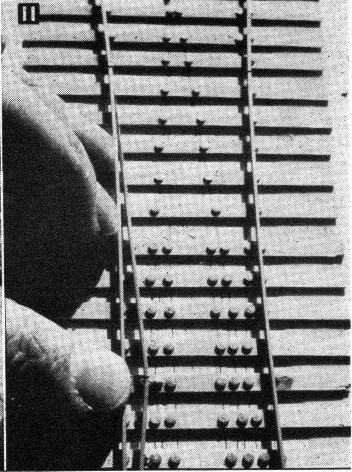
The switch blade is then filed to shape, and the removal of the 'wafer' of metal during fabrication will reduce the overall length to that desired. The double switch blade is then carefully cranked, and positioned as with the diamond, using the steel rule as a guide. (Photos Nos. 10 & 11).
An interesting feature of double slips is that the pairs of switches at each end of the unit are connected to, and worked from, a single lever, so that two levers, one at each end of the double slip, are all that are used to set any road through the slips.
Special Formation. (Photos Nos. 6 & 8)
Here and there, despite the modernisation programme, there are odd formations which have survived from the past. These are now so rare that they may well appeal to modellers of the unusual. There is always a reason for these specially made units, the double diamond crossing through the middle of a turnout being necessitated by a South Eastern single-line arched bridge, and the other inside and outside combined single slip resulting from the severe curvature of the main lines. It is interesting to note that the outside slip has check rails formed from switches bolted to the backs of the running rails.
|
|
|
9 Barton Street crossing, Gloucester. A combination of double junction, interlaced turnout, and crossover road. |
10 & 11 Using the steel rule to align the obtuse crossing nose in model diamonds and slips. The stock rail is checked for correct Aset" once the obtuse crossing nose is positioned. |
|
Design of Junctions
In the prototype, junctions are designed with the assistance of data sheets giving standard leads and similar information, combined with scale drawing. From the resulting calculations, a parts requirement is drawn up. It will not have escaped the notice of readers that the model will also require some accurate drafting work. It is impossible to avoid this as there are so many critical dimensions dependent upon each other, and guesswork is certain to lead to difficulties.
The answer to this problem lies in the use of templates. The Group has produced a series of these covering most of the formations likely to be encountered. Not only do templates solve the problems of drafting. they also open up a new field of modelling all their own, as the various possibilities of a particular situation can be checked without the expenditure of track material. Furthermore, such a layout will be correctly proportioned and guaranteed to work. The armchair modeller will have a field day, but the more practically inclined will find that the use of templates on the smooth surface of the baseboard will solve all their jig problems.
Conclusions
From the techniques advocated in the series, it will be realised that not only is Protofour a new standard, but a new attitude to the production of scale model railways. The Group has tried to show that, given sound basic information and correctly designed equipment, completely accurate and authentic scale model railways are not only practicable but within the capabilities of the ordinary modeller. It is no longer mandatory to accept compromise standards in order to model scale railways at all.
Although the Group has concentrated initially on wheels and track, this is not its only endeavour. The Group's title has therefore changed to the Model Railways Study Group, and with the Editor's permission, the results of its enquiries will appear in these pages from time to time.
Meanwhile, sufficient information has been provided to enable those interested to construct authentic scale model railways with every probability of success, and at the time of writing at least one modeller has done so. The Group would like to take this opportunity of thanking readers for their forbearance through this series, and to wish them happy and successful future modelling.
The Protofour Principles of successful Scale Model Railway Construction
A. Basic Track and Wheel Relationships
Wheel Tyre and Rail Head contours must be matched, and correctly proportioned for the standards in use.
Wheel Spacing on axle (BB) must be correct.
Track Gauge (TG) must not be less than the nominal value, and may be widened for curves.
Check Gauge (CG) measured from the face of the check rail to the face of the outer running rail, must never be less than the nominal value.
Crossing Flangeway (CF) between wing rail and vee, must not deviate from the nominal value in any circumstances.
B. Track Alignment
Track must be controlled in three axes
a. Laterally, by maintaining rails to gauge.
b. Longitudinally, by correct alignment along the roadbed.
c. Vertically, by maintaining the rails at a constant level above the roadbed, and level in relation to each other.
The baseboard, by controlling factors b and c above, is thus a critical factor in itself.
C. Switches and Crossings
Turnouts, crossings, and combinations of these, are formed from only three basic units : Switch pairs, common crossings, and obtuse crossings, joined together as required by closure rails.
Crossings and switches are units built to stock sizes, laid to standard dimensions, and chaired and timbered to standard patterns.
In model switch and crossing assembly, the nose of the common crossing should be used as the reference point for all dimensions.
D. General Constructional Principles for Switches and Crossings
The layout of the turnout always begins with the establishment of the angle of the crossing. either by scale drawing or by reference to tables.
The construction of turnouts and crossings, whether as individual units or as junction formations, should always be carried out in a jig.
The assembly of parts should always commence with the accurate positioning of the crossing nose.
Where several crossings are incorporated in a formation, (e.g. diamonds and slips) the vees must ALL be positioned before further assembly takes place.
In diamond crossings, where crossing flange-ways are simultaneously required for both running rails, the NOMINAL track and crossing flangeway gauge must be adhered to as closely as possible, with NO gauge widening for the curvature of the road.
All flangeways and running rail settings must be checked with gauges before finally soldering. Settings should never be accepted because they appear to be correct.
Complicated formations and minimum radius curves are virtually incompatible. As model railways generally incorporate curves with minimum radii far below those acceptable for the prototype, complex trackwork on sharp curves is automatically beyond reasonable limits for satisfactory operation. and should not be attempted.
| TRACK | Prototype | Equivalent | Millimetres | Inches | Checks | |||
 |
TG | TRACK GAUGE | 4' 8½" |
18.83 |
18.83 |
.741 |
Min |
G |
| GW | GAUGE WIDENING | ¾" |
.25 | .22 | .009 | Nom. | - | |
| CG | CHECK GAUGE | 4' 6¾" |
18.25 | 18.15 | .715 | Min | G | |
| CF | CROSSING FLANGEWAY | 1¾" |
.58 | .65/.68 | .025/.027 | G | ||
| WHEELS | ||||||||
| BB | BACK TO BACK | 4' 55/8" |
17.87 | 17.67 | .696 | Min | G | |
| BB+EF | CHECK CLEARANCE | 4' 63/8" |
18.25 | 18.15 | .715 | Max | - | |
| TW | TYRE WIDTH | 5½" |
1.83 | 1.85/2.00 | .073/.079 | - | ||
| EF | EFFECTIVE FLANGE | 11/8" |
0.38 | 0.40 | .016 | MAX | - | |
| ESSENTIAL COMPONENTS | P |
WHEEL TREAD CONTOUR - BS 276A EQUIV. | ||||||
R |
RAIL HEAD CONTOUR - BS 95R EQUIV | |||||||
The plan is full size 4mm for a 1:7 double slip with "B" switches.
Copyright - Model Railway Study Group, reproduced with permission.
Back to Magazine Index, Back to Site Index.
K Norgrove 25/04/03