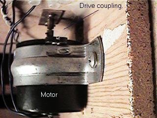
The turntable bridge sits in the pit supported by the ring rail and located by a fixed pivot pin which enters a bearing in the centre of the pit. This pivot pin carries a spur gear fixed under the centre of the bridge. A drive shaft is installed in the turntable pit floor offset from the turntable centre such that a spur gear on the top of the drive shaft meshes with the spur gear under the bridge when the bridge is lowered into position. The drive shaft carries a sleeve coupling at the bottom. A Hankscraft display motor is mounted vertically under the drive shaft so that a cross pin through the motor shaft engages in the sleeve coupling.
Motor held in place by a pipe clip, supplied as the mounting when purchasing the American Switch and Signal style switchmotor, drops out when screws loosened. The Switchmaster mounting arrangement could also be used but would be a little harder to adjust vertically so it would be important to establish the required length of drive shaft carefully. (Photo 2)
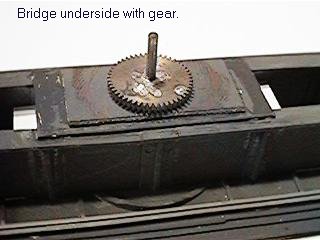
Bridge; Any ready made, kit or scratch turntable bridge can be used (Mine is adapted from an Airfix/Dapol kit). To work correctly the bridge should be supported off the ring rail. Usually the kits are provided with a two wheel carriage at each end, one of these should be pivotted (equalised) to give three point support to the bridge.The main bridge pivot pin needs to be rigid and vertical to keep the table accurately centered and to give a constant mesh for the gears.I used a piece of copper clad paxolin (unetched circuit board) approximately 25mm square glued to the top and bottom of the girder assembly and soldered the pivot pin in place. The spur gear was then soldered to the pin immediately below the girder. The pin can be any convenient diameter to suit the spur gears you are using. Mine is 2.4mm (3/32"). Approximately 1/2" of the pin should protrude below the gear in order to locate in its bearing in the pit bottom. (Photo 3)
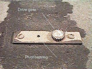
Pit; This needs to be constructed to the depth appropriate to your table, the pit floor should be made of ply or chipboard at least 1/2" thick to provide good support to the drive shaft. This shaft is supported in bearings in two brass plates screwed above and below the pit floor. The top plate carries bearings for the table pivot and for the drive shaft. A brass plate of at least 1mm and better 1/16" thick should be used to give a robust bearing and the bearing holes should be carefully drilled to suit the shaft diameters using the spur gear set as a guide to ensure correct mesh. I used a 2:1 gearset from Mikes models installed with the larger gear on the bridge. (Photo 4) This gives a realistic speed with the 4 rpm hankscraft motor and ample torque to deal with heavy locomotives. A 3:1 gearset should also be OK but higher ratios would slow down the table too much. Sharman wheels gearsets are the easiest to get here in UK, equivalent gears are available from NWSL in Seattle.) Another pair of holes in the bearing plate allow it to be screwed in place, location of these screw holes is not critical, just keep them away from the gears.. A similar plate with only one bearing hole should be made for the underside of the pit floor.
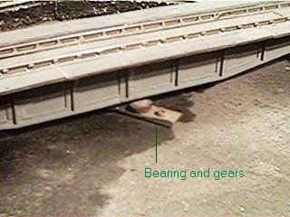
To install the bearings first drill vertically through the pit at the turntable centre the same diameter as the bearing hole and use a piece of shafting to locate the top plate while you screw it down. A second vertical hole, bearing size can then be drilled for the drive shaft, using the plate as guide. Use a piece of shafting in this second hole to locate the bottom plate and screw that in place. Both plates can then be removed, the holes in the pit floor enlarged a little so that the shafts will turn freely and the plates screwed back making sure to use the same screw holes.The smaller spur gear can now be soldered to the end of a length of shafting and installed in the drive shaft holes with a couple of washers under it. The height of the gear should be adjusted so that it meshes nicely with the bridge gear when the bridge is sitting on the ring rail. Ensure there is a millimeter or so clearance under the bridge gear so that all the weight is carried by the ring rail. (Photo 5)
Once this adjustment is made and the table and gears rotate freely, the drive shaft can be cut to length leaving 1/4" to 3/8" below the floor. A socket now needs to be soldered to this shaft to couple with the motor shaft. The motor shaft is 1/8" diameter and comes drilled for a cross pin, so what is required is a slotted sleeve which will be a loose fit over the motor shaft so the slots engage the pin. Make the slotted sleeve from 5/32" inside diameter tube and then arrange a bush from smaller tubes to give a good fit on the drive shaft. This should be soldered in place to retain the drive shaft in position and to transmit the torque. As an alternative a ready made brass universal joint can be used but as this coupling has to transmit a lot of torque press fit plastic universals as used for locomotive drives will not be strong enough.
A motor mount should now be arranged to hold the motor vertically under the pit floor with the coupling engaged. I used the pipe clip supplied with the motor screwed to a strategically placed piece of timber. (Photo 2)
American Switch and Signal
Route 4, Box 370,
Winamac,
IN 46996
tel:219-946-7667
their model SM-1 Slow motion switch motor
and Builders in Scale
P O Box 441432
Aurora, CO 80044
tel:303-699-1822, fax:303-680-6088
their "Switchmaster" slow motion switch motor.
North West Short Line
Box 423 Seattle
WA 98111-0423
USA
tel:(206)-932-1087
3/32" shafting, stock # 2093-4 0.5mod spurgears, 2.4mm bore, 12 tooth, #77612-6 24 tooth, #77624-6
and Sharman Wheels
Glan-Henwy, Golan
Garndolbenmaen,
Gwynedd LL51 9YU
tel: 01766 530773, fax: 01766 530259.
Go to turntable electrics Back to turntables Back to home page
Keith Norgrove, updated 10/9/98.
Copyright Keith Norgrove.
Last revised: August 27, 2003