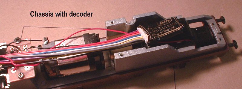
As my layout operates on DCC I needed to fit the loco with a decoder. As can be seen in this photo the chassis design allows plenty of room.
There are, however a couple of issues to examine.
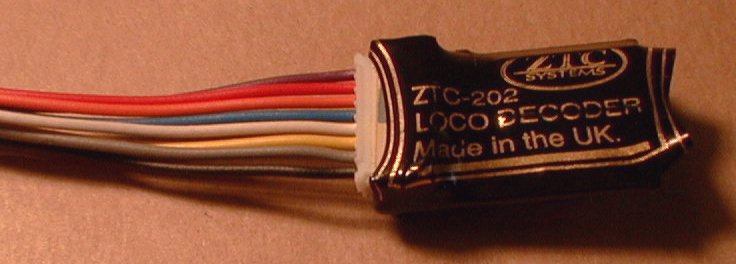
Firstly, in view of the amount of space available I decided to use the larger ZTC202 decoder, thus keeping my stock of small decoders for those locos where they are needed and preserving the option to install lighting in the future.
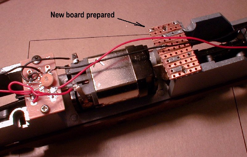
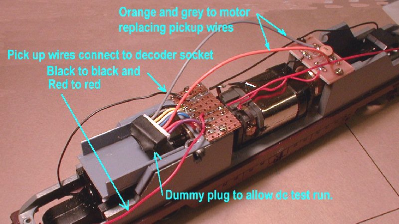
The existing circuit board in the loco carries a capacitor and two chokes in the motor circuit but does not have any facilities for connecting the additional wires for the decoder. I decided to retain this board and thus removed the pickup wires from it replacing them with the decoder motor connection. Once the pickup wires are removed it is evident that these wires are different lengths on each bogie and will only reach a circuit board at the same position in the chassis as the original. Because of this I moved the original board to the opposite end of the motor and fitted a new board for the decoder and pick up wires in place of the original. This new board being simply made from a small piece of stripboard.
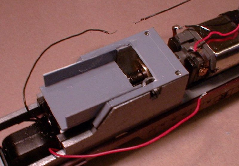
A small plasticard cradle was made up to keep the decoder out of the drive shafts and then the pieces assembled and wires connected. After a quick track test with a dummy plug instead of the decoder to ensure no wiring errors the decoder was fitted and programmed.
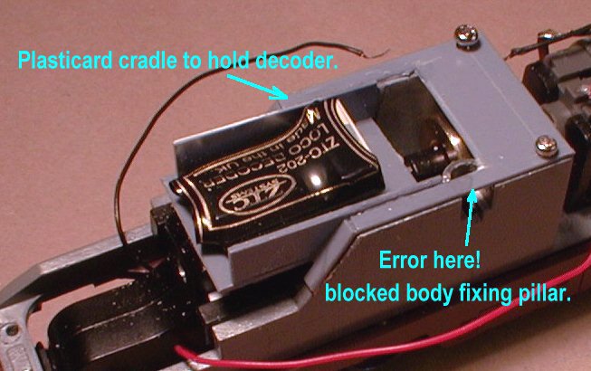
Putting the body back on revealed that I had overlooked the body fixing pillars when making up the plasticard cradle and I had to remove the obstruction!
The following picture sequence should make this process clearer:
|
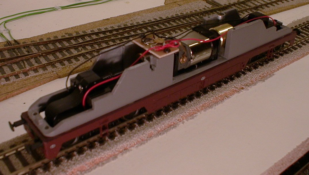
Photo-2, Decoder laid on chassis showing available space. |
|
Photo-3, Chassis with new board in preparation. |
|
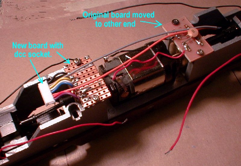
Photo-4, Original board moved to other end of motor and new board tried in position with dcc socket connected. |
|
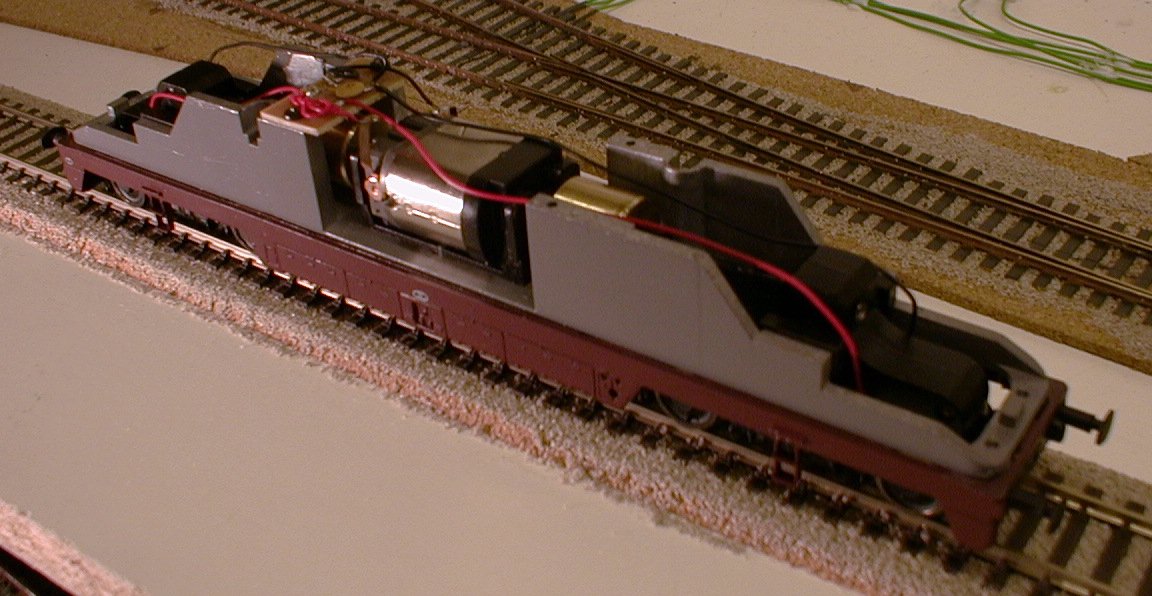
Photo-5, Plasticard cradle to keep decoder away from cardan shaft. |
|
Photo-6, Plasticard cradle with decoder. |
|
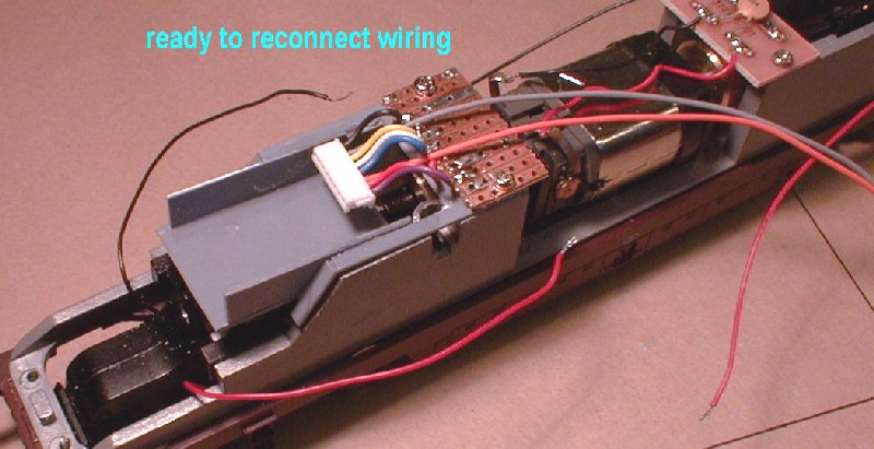
Photo-7, Cradle and new board in place ready to reconnect wiring. |
|
Photo-8, Wiring connected ready for trial run with dummy plug in place, wiring checked with multimeter first! |
|
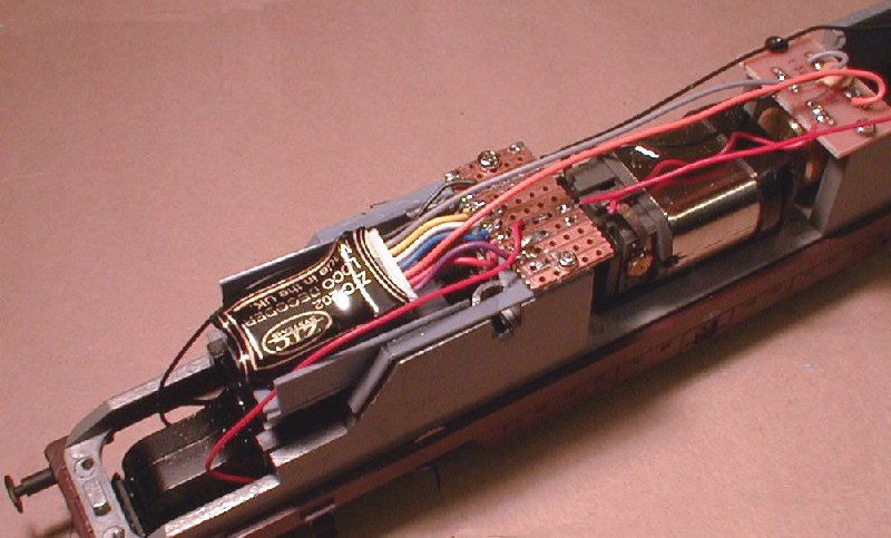
Photo-9, Decoder installed and wiring tidied up ready to fit body back on. Programmed to address 17 and running again. |
Copyright Keith Norgrove.
Last revised: August 27, 2003