|
Cast metal Kits A series giving the "knowledge" for successful construction R. C. Ormiston-Chant This series in 5 parts was originally published in 5 parts in the Model Railway Constructor from February to June in 1972 (I think that was the year), Robbo was a stalwart of the Manchester Model Railway Society and well known in the letters pages of the magazines for a long period. I'm sure he would be happy that his article remains available. KN. |
|
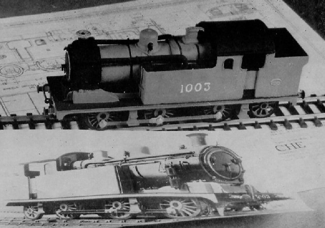
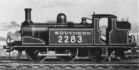
CAST metal kits, made by a process of centrifugally casting parts in a soft metal having a low melting point, have been with us for a long time now. Nucro once made some wagon kits, now somewhat treasured, for a short time, but it was the dark deed of Ken Keyser in 1956 that really set the ball rolling. Furtively he threw at a derisive public the first kit for the GWR 4800, later 1400, Class 0-4-2T locomotive, the kit being to 4mm scale. From then on he was a made man and soon to be imitated by Bob Wills. BEC of Tooting followed with more locomotives particularly in 3mm scale and later returned to the road with tramcar kits though trains clang and do not toot. George Mellor eventually joined in by making the LNWR his particular preserve, both in 3 and 4mm scales; he has also most successfully modelled the other worthwhile railways, the GWR, MR and CR etc. Other firms have indulged, often in other fields, while Peco have produced loco kits for N gauge, Anbrico and Brackenborough are devoted to the road, the former excelling in exquisite kits for buses ancient and modern. Yet again some firms have used these cast parts in a secondary role as may be seen in the PC Coach Kits and one way or another the process is well entrenched as a sound, accurate and reliable means of producing small castings in either small or large quantities. My own regret is really that there is not an adequate range of minor fittings and mountings done in the metal, many parts do exist often as corollaries from a complete kit pattern, K's and GEM will offer any part this way though most unfortunately Wills cannot for certain reasons, a pity as he goes in for some interesting items and casts to very fine limits with a highly developed machine. If the problems attendant upon the use of multi-cavity dies (producing a number of different parts per cast) could be solved I feel that modellers would be encouraged to adventure a little into the scratchbuilt world using these cast parts, often of standard components, for the troublesome things beyond the skill of the novice, or even experienced, chap. However, Bob Wills pointed out to me that while he makes some 32 kits these yield almost 50 locomotives without radical alteration, for example, the kit for the GWR "Hall" can be readily altered to give No 4900 or the "typical" Hall, or the final development with through frames. And the LNER K3 2-6-0 gives two versions, GNR and LNER simply by altering the cab and one or two minor details with a more major operation on the tender. Some of his kits are planned with this in mind, such as the SR Mogul" or the CR Shunting Loco. A brief scan of the W&H Catalogue shows that there are 110 types of locomotive alone available in all scales from 2mm up to 4mm including variations built into the actual kits. Add one's own variants and one has a lot of motive power. "And still they ask for more," I quote Bob Wills. Apart from motive power there is a good family of rolling stock along with such diversities as signals, water cranes and hand cranes for goods yards. The list is formidable when worked out in detail. While I came to cast kits quite late on, only about 10 years ago, I have so far turned out over 50 locomotives and several other items including trains which I dislike and George Mellor's Yard Crane which I adore, likewise the vintage buses by Anbrico. Some techniques still elude the makers. The kits are produced by making dies from a Master Pattern, and hot metal is then run into the dies by centrifugal force. A one-piece boiler casting so far eludes the hobby except for Wills tiny SECR 0-6-0T, and the same maker had to finally cast the sides of the LNER A4 Pacific in four pieces before it came out right, but on the whole almost everything In the railway field could be cast if it was economic to do so. Unlike the Editor I have never punched a hole in a kit during soldering though I use this means almost exclusively down to the tiniest part, but then I could believe anything of our worthy Editor! As you gaze across the murky wastes of an exhibition your eyes alight upon him and you exclaim "There is a man who melts a hole 78 thou diameter in the third cabside of a Ruritannische Statsbahn 0-7-2T ! ". As he edits this we had better proceed to more useful data. [Well, we can all makes mistakes!—Ed.] I am human and in early days I did vaporise a whistle or two, but being human and of a thinking mind I thought it out, my solution will be described. So, good friends, let me point the way to Nirvana while you all make off hastily in the other direction.
Safety Surprisingly enough while the soldering technique may seem rather harrowing (see later), the risk of scalding is very small, if the job is that hot you are heading for a melted kit, so there is a built-in warning for you. If young children are about the house keep all chemicals out of their reach, but as toddlers and fine models do not mix, parents will have their own routines here. Ways and
means When I first began I took one maker at his word and glued the parts together. Though I used the best Scotch Glue and even our dear friend "Seccotine" I made no progress because the glues will not bond on to the metal. Therefore, one should for once disregard the maker's instruction sheet, and NOT try to glue the parts together. So I turned to adhesives. There are a large number of these falling into three broad fields, the Epoxy Resins, the Petroleum Base Cements, and the Cyano Acrylates. Of the first, Araldite is long established and a very good "goo" though there are now some that will cure at room heat fairly quickly, but they are quite costly and not common, an exception is Isopon which I have not used myself but understand to be good. The Petroleum Cements have the most popular appeal, being easy to use and easy to buy. The best used to be "Pafra", which was a lovely thing free from stringing and most versatile in application, but it has gone alas! Today we have such media as Bostik No 1, Evostik, or UHU, while these string somewhat they are good sound adhesives of general value about a model railway. The first named are both impact adhesives whilst the third is a simple contact adhesive. Cyano Acrylates are a new concept and while they are not freely available they deserve mention, if only to encourage Douglas Kane Limited to pack them for us modellers. They act by means of the free ions present on the surface of most hard materials and many plastics as well. When air is excluded the cement goes into action usually very quickly, it is immensely strong and proof against all our ills. The most spectacular is the most expensive, Loctite IS 06, this acts in half a second and will really stick solid a host of troublesome things, such as nylon to glass, polyethylene to metal etc. If it were readily marketed in small amounts it would be a third hand in securing parts in line whilst they were finally soldered, something of great value in kit assembly. Its price is very high, about Ł1 for a 3cc bottle, but as only small spots are used it is in fact a thrifty item. Another Loctite product, Retaining Compound, is for bonding in place bushes or wheels and so on. Thus I use it to fix worms on to motor shafts and wheels on to axles; I never use the grub screws (if any) these days. As one small drop secures any model bush or gear the 3cc bottle goes a very long way for its 9s 0d or so, mine is in fact 2 years old and I use it steadily. But as I remarked before these adhesives are still much an industrial matter, wherein they are tailored to suit the job, and if only the makers would pack them in small tubes, say about 1cc, I am sure they would appeal to the modeller wanting to keep kit parts in line or secure worm wheels on to axles when a force fit would be normally needed yet a difficult thing for the ordinary chap to attain. |
|
Finally we come to solder. This is a special solder designed to suit the kit metal which melts at around 100 deg C. Thus the solder melts slightly below that. Two firms supply it, EAMES and George E. Mellor. One packet from either will do a medium-sized job such as a 2-6-0 or a 2-6-4T, it depends on the finish of the cast parts (see Later). A special flux based on phosphoric acid is required, this also comes from EAMES and from general suppliers in the form of "Soldaflo". there may be other brands unknown to me. Commercial acid of 40 per cent concentration can be used though it leaves an oily waste behind which is annoying. It is by far the best general flux for all of our modelling, being safe for electrical work and free from any corrosion and suitable for all normal soldering metals including stainless steel, for which it is the only tinning flux. As the acid is also a rustproofer, it is the basis of the modern ones, it particularly recommends itself for models using steel or tinplate as it will not cause later corrosion like Bakers Fluid, and will in fact rustproof bare steel or iron surfaces and edges. Moreover, once it is washed down it makes a fine base for painting. However, on the kits, if it is left for any time, it forms a hard, grey powder that stops paint from drying, and you will see that a strict washing routine is needed. In order of speed, assuming that a kit could be assembled through out with the Loctite, that would win hands down, a couple of seconds for each joint with the least preparation needed, just a scrape clean. In fact, using IS 06 one could do a big loco for about 50p, which is not much, you know! Then comes soldering, which has the great virtue of doing its own crack filling etc. After that the impact and contact adhesives, but which need crack fillers. Finally, Araldite, which must be heat cured in between each sub assembly, though it can be tailored to fill as well. Techniques for adhesives Impact and Contact cements Epoxy Resins Under no circumstances may a cast kit assembly be cured in an oven, this will collapse the assembly by softening the metal. Oven curing is done at 65 deg Centigrade and this is far too close to the metal melting point. Epoxy Resins may be used to fix parts on after a model has been painted, the contact area being carefully scraped bright. The others cannot be used in this way except by meticulous care as the slightest amount of "goo" straying on to the paint will promptly strip it. As you may thus ruin many hours of patient livery work you should think carefully first. If you make a 'boob" with the Loctite you may be able to soften it locally by heat and break the joint, be careful though. If you do so with Araldite you have had it. There is a special stripper attacking it but one must leave the whole job for some days in an atmosphere of the stuff, so this is not on. The Petrol Adhesives are easy, apply some ordinary paint stripper such as Polystrippa to the bad joint, wait five minutes and then gently ease the two apart, a small screwdriver may help. Clean off all the muck and remake the joint on to bright metal again. With Low Melt solder it is even simpler, if you own a Butane Cigarette lighter. You set that apparatus to a high flame, hold the bad joint over it just clear of the tip and keep it moving, up and down the joint, the job will warm up and finally the joint will part. Arrange that gravity lets one part fall away. Immediately remove all heat and cool the parts, clean down to bright metal and resolder. I have stripped most of a complete loco this way though I had to refill the lighter twice! The important thing is not to let the flame dwell but move unceasingly along the joint and around it. Crack filling After treatment I cannot trace any suitable etchant for the metal, neither Chromate nor Plumbate are at all suitable, being intended for cupreous or ferrous metals in that order. In fact I found by experiment that Chromate flakes off if a model expands slightly with warmth. A lead ing paint maker told me that I was wrong so that was that! He advised what has since many times proved the ideal way. Wash the model in a degreasant. Here Lighter Petrol is a cheap and very safe and efficient medium to use, it will not attack plastics or the varnish on motor windings etc, so it is safe to bath a complete loco in the stuff to clean it and I have done this many times. (However, be careful with toys such as Tri-ang, you may dissolve the lining etc which is a Spirit paint of some sort, just wash the mechanism only.) When the model is dry again,
slightly thin down a good plastic enamel (GLOSS) such as Humbrol or
Joy, or a Lacquer such as Valspar. Apply a free but not excessive coat
over the model. Allow two days to dry and harden. You will then see
that in many places the paint has soaked into the model surfaces, in
so doing it has sealed them all with a good fine coat of neutral
plastic, just right for the railway enamels. Compatibility is at a
maximum and the surfaces are free from further absorption. Naturally
one chooses a colour sympathetic to the final livery, bearing in mind
that black laid on after will obscure anything, so you can paint the
entire model, inside and out, green or crimson or whatever. In fact,
my sealers are: This leaves only Soldering to come, and I have a feeling that there is an impatient queue waiting. But even so, try the other ways, say on Ken Keyser's wagons, because you will learn a lot by them if you sample each, and the wagons will not take too long, also they will survive a rough job as they are not prime movers. |
|
Low melt soldering With normal tinning solder one gets clean surfaces and applies flux to keep them so under heat. One then heats up both parts adjoining and runs in a line of solder which makes a molecular lock on to each part just at the joint. Low melt solder does not work quite that way. One cleans the two surfaces, reasonably so anyway, the flux will take care of all but sheer filth or the dried-up deposits from old flux (note the last). One floods, repeat floods, the joint with flux and presents the edge of a bit holding the solder to it. The heat of the bit boils the flux which then melts a tiny amount of the kit metal on each face and the low melt solder runs off the bit into this wee puddle to form in effect a Fillet Weld. I discovered this when many years ago I misplaced a chimney or something and duly "flamed" it off with my lighter. I then saw that where I had soldered the piece there was a little ring indented into the parent assembly, where the kit metal had puddled, so I realised that a proper weld had taken place. After that I frankly exploited the phenomenon mercilessly and still do so, but it requires some hours of practice to tinker about in this manner. |
|
|
|
Just bear in mind that when you use low melt solder on a joint in kit metal you are making a proper little fusion weld. This is why the method is not so hot with hard metals, a full weld does not, of course, occur. It also explains why normal tinning solder is not suitable for kits, if a proper bond was made the kit parts would be melted wholesale and destroyed. The flux is the worker here, as by boiling it melts the kit metal and at the time draws the solder off the iron into the joint to fill it. So may the canny modeller fill all cracks, even whoppers. I have backed up a gap of 1/16in with strip wood and filled it with low melt solder when I did not have any kit scrap to make a packing piece. It is well to try out the process on some old stuff before you first jump in so that you get the feel of it. Therefore, choose a kit that offers alternative parts and use the unwanted ones as test pieces. Having made your first ever joint on a suitable object, clamp it hard in the vice and try and wrench the attached part off with pliers. If a union of about 1/8in square is sound you will have a real job on. If, however, the bond is not properly made the two will come away very easily indeed, so you will be in no doubt as to your success or failure. Now try a bit of crack filling. Choose two pieces that offer a nice gap when joined. Put the smaller edge to the larger and place some flux, put on at one end of the seam a small blob of low melt. If you are satisfied with alignment, go to the other end of the seam and having flooded the lot with flux take up a good iron full of low melt solder and work it slowly along the seam, until you reach the first blob. When you hit that the other end should be cold, this way the two parts are always supported in line by hardened solder. Now reflux on the other side of the joint, and run the iron along slowly, letting the placed solder gradually melt through until it shows a bright line. If you want a good supporting fillet where it will not show, you can instead feed more solder in to make one. This is of great value in supporting things like footsteps from the back. (If possible in such cases I like to put in a wee gusset of scrap kit metal, it saves a model coming back after a week minus its steps.) After a little practice you will find the art of 'teasing" the solder through a seam to make a really neat and trim joint that needs no further attention, in this respect there is a massive advantage over normal solder which cannot easily be managed in this way. To put a long tankside to a running plate and finish with a perfect corner joint is very satisfying and usually done at about 2in a minute inclusive of preparation, you cannot do better than that! Troublesome boiler joints cease to exist, as they are deftly overlaid with solder much as a welder builds up over one of his joints, the excess then being filed back to profile (known in full-size welding as Flush Grinding). The last exercise is a really shaggy one, the soldering of the whistles (etc). Some folk like to put on brass whistles like the real things and ditch the kit ones, but as whistles never did show 'brass', not for long anyway, there seems little point in this. In your long suffering test piece, drill a hole for the whistle. Countersink this hole till it shows about twice the diameter. Flux it and quickly wipe round it a small bead of low melt solder, about a pinhead or so in size. Pop the whistle in place, easing the hole if need be, and flux again. Now put the flat of the iron near the whistle on the parent surface, NOT touching the whistle. In a second or two the flux will boil, the solder around the whistle will melt and flow in to meet it. Remove iron. So long as you do not hang around too long, particularly after boiling ceases, the whistle will not melt fully. only slightly in the hole. It will be secure, and probably broken off during the first week's service, so back to brass ones! I said the above was the last exercise but you might as well fix a handrail pillar. Thus your test piece ought to be thin, I have in mind the alternative boiler shells supplied by Wills in certain kits such as the Caley 0-6-0T (which is the ideal beginner's model anyway, and a charmer for any layout). We can use a split pin as it stands for the test so simply pop it in the hole, and spread out the tails underneath. Scrape a little each side of the tails and put on some flux, not much. Take up a good blob on the iron and drop it across the split of the tails so it flows each side and forms a bridge across the split. Thus when the pillar is normally standing proud of the boiler casing it cannot be pressed back into it accidentally, if the little bridge is sound. It is no use trying to just solder the tails down, the low melt solder will not hold on the split pin copper plating, you must actually make a bridge across the pin. Also I emphasise that the tails must lie flat inside the boiler shell. This summarises the basic technique of using low melt solder. If the above routines are tried on one spare part only, the average chap will gain experience to take on the model proper, and he can, of course, undo the job and remake it to his heart's content without worrying about the eventual results to the test piece. That may be either framed as a precious relic or best of all crushed in the vice and used to ballast a plastic wagon or something. Some kits offer so many spare parts that one collects an army of "useful things". I have built a dozen GEM LNWR 4-4-0s and thus acquired 24 spare tender buffer beams and numerous "Precursor" splashers, which last are very useful as stocks for other large splashers! My fellow GWR men will be horrified to learn that six ended up on a hard metal "Hall" class loco, they were just right when cut down! Another 6 were given to a friend to make his Wills SR Mogul take 6 ft scale wheels. I will draw a veil over the possibilities of chimneys and things, I have a drawer full. Seams Butts |
|
|
|
Boiler mountings The reason for the hole is that you are in fact only soldering the rim of the skirt, and if there was no hole to the interior of the boiler unused flux would be trapped in there under the mounting. Hence either there would be a tiny explosion as you finished the run round, it could blow off the whole mounting or, worse still, the flux would slowly work through a weak spot in the soldering and emerge in a nasty blister just after you had finished the livery. The hole allows the unused flux to escape and also lets in cleaner later to shift any left. If you want to drill out "solid" chimneys, start small and work upwards in size by easy steps and go very gently; I always finish off by handscraper, using the Skewdge referred to later. Don't try and hollow out domes, you need the weight which is one of the great virtues of cast kits. Fixtures. Handrail pillars
and such like. Tenders and such merely need advance planning to ensure that all pillars are in place while accessible, this might be done at any stage up to the fitting of the coal plating or tank top. When inserting the pillars, put through a short length of wire and insert the "Grudger" as per sketch, this holds the pillar and wire off the face by the right amount, spread the pin tails and bridge with solder. If you must use machined brass pillars then you must very finely tin them and fix them as per whistles etc. and again pray. Some locos such as GWR have one or more pillars on the smokebox door-ring and these must be threaded on to the complete handrail wire before it is fitted to the side pillars. Thus these end ones cannot usually be soldered in but the wire if bent neatly should hold them in place. LMSR ones can be fitted into the smokebox door well beforehand, but in that respect the LMSR or rather the MR before it was very sensible, alone among British railways. (All the others had the handrails far too high up at the front, you could not use the things!) Cab pillars are those long handrails from cab floor to roof on some modern locos, and some old ones too. such as LNWR. To fit these, pop mark the positions on the cab step top and cab roof when the last has been fitted. Drill the lower hole at an angle inwards, about 10 degrees or so, you will not then emerge below in front of the step Drill the roof one dead vertical. Bend the wire at the bottom for the angled hole and drop it from the top downwards. Cut it neatly off, flush with the roof and spot with a pinhead of solder underneath, this holds it and looks like the little bush or palm used in full size. You may wish to put a spot of solder at the bottom as well, and possibly where the wire passes a beading of the cab look out; do this last one most gently to avoid melting the tiny lip. Grab irons are fitted much as the handrail pillars,, in that a small bridge shape like a paper staple is bent up of wire to the necessary length and spacing of legs, allowing 3/16in over on the legs. These are put in the holes, the iron held out by the "Grudger" and the legs underneath or inside bent over like a paper staple. Then they are bridged with solder. In some tenders this will show at the front edge of the sides, eg LNWR ones, but here one must sacrifice a little neatness for security, as one cannot just sweat the legs in and cut off flush as with hard metal sides. Lean a shovel against the side to hide the mess if you like. Lampirons and the collection of hooks etc on the back of certain GWR tank loco bunkers are fitted much the same way, being formed of flattened wire and secured inside the model by bridging bent over tails. If on a GWR Pannier Tank do not forget the bucket. From this modellers may deduce how to fix other details of their choosing. Things like opening smokebox doors and what not always annoy me, fit them if you must, but as there are no tubes inside a model boiler, which is not a boiler anyway but the casing of one, there seems little point in having access to them. Unless it is to permit the escape of fumes from an outraged electric motor, the actual occupant of the "boiler"! Old hands will recall the ever adorable Bond's Peckett Tank in Gauge 0, the "Bonzone", and a fine model it was. I incurred parental hatred by opening the working sandbox lids and inserting sand therein. This is unlikely on a cast kit anyway. (Well, dammit, I dried the sand first, a driver at Manchester Central told me to always dry the sand!) I am not going to say anything about the fitting of toy mechanisms in kit models, if possible always use a Tri-ang mech. because it is 100 per cent on the ball and easily converts to scale wheels, the wheelbase may be a bit off at times but when you are old and wise you will know how to make your own mech. Until then be sensible, However, GEM has issued some kits having mechs. in bits and these are emphatically best assembled by low melt solder. The only sure way is to afford a pair of ground parallels from a tool dealer, get ones about 5in long, and invest in a good quality plate glass mirror and length of 0.125in silver steel. Cut the last into three equal parts, filing a neat lead on each cut end. Solder the spacers to ONE frame only, usual techniques apply. Assemble the lot up with rubber bands, not too tight but nice and firm, and slip in the bars through each pair of axleways. Lay the lot on the parallels with those clear of the frames, and adjust the latter until all bars are sweet in the holes, then flux the unsoldered side and spot it, check again, and finish off. This is rather over-simplifying the job, but I cannot really offer better help even in a dozen pages. Do the loco body first, or rather do the tender first then the loco body, and you will have gained the "feel" to get the frames right. You may be able to dispense with the parallels etc by putting good flat track on the mirror and wheeling the loco with the frames banded together as before. Then you can pop her on the track and adjust the wheels until they are sweet, but it is a most tricky way to my feeling; I have not tried it. The main fault with the GEM frames is in the axle ways being in soft metal and not bushed like Wills. I have in fact bushed GEM frames but am not keen to encourage others to do it unless they know how to, in which case they would not ask. IF you buy a No 27 drill of top make, in high-speed steel only and IF your large drill brace is really good, eg Stanley double pinion, and IF you have a dead-on eye for level and squareness, then you can clamp the frameplate firmly in the vice and carefully open the holes to take Jenning's Bushes ("Tri-ang Conversion bushes"), afterwards pressing these gently in with the vice jaws. I wish George would do it himself! Wills frames are cast as boxes and need no comment other than that you make sure that they fit tinder the body without that twisting them. So I will conclude the actual assembly matters by looking at this one. As you put up the running plate to buffer and drag beams check the alignment, but even so as the boiler goes on twisting can occur, the cast parts are full of little stresses which emerge at odd moments when least expected. My method petrifies my friends in that I clamp the one end of the body firmly in the vice and put a special hand vice I possess over the other end and heave the lot square. DON'T do this! Secure the model in the vice by the front buffer beam before any brake hoses etc are fitted. Grasp the cab evenly all round within the U-shaped hand, making sure you bear evenly on all parts, and with your body, not your arms, twist the model slightly overtrue. Let go and look. The resilience of this "soft" metal is surprising and two or three attempts may be needed. When she is happy you may have strained an odd joint or two and can remake as needed. I always do for several but that is how I find out the weak spots for my customers. I might say that one gentleman, in offering a kit for painting, assured me it had been assembled on a plate glass. Oh, dear! Take my advice and do it by eye and sort out the crinkles later. I had to take his apart in places to get it true. Remember that the best of them cannot always guarantee that these soft metal parts will stay dead true after packing and you must sort out some bugs yourself. |
|
The toolroom Vice Files Twist Drills Pliers and Sidecutters Tweezers Rule Scrapers The most useful scraper of all you must make yourself, by killing one of the new needle files, the one called Barrette, having three faces, only one of them armed. (Hence this file tends to wear out quickly anyway.) When this one armed face is ground smooth and all faces stoned up you end with a most excellent tool which I call the "Skewdge", a cross between skewer and gouge, it does a host of odd jobs about any metal or plastic model from getting flash out of window openings to clearing internal corners of excess solder, it is at its best on female curves such as cab lookouts, the frame openings of many tenders and so on.
The Vanishing One is drawn here, along with the 'Grudger", both being easily made from oddments; the "Grudger" may be of wood but the VO must be solid stuff. I call it thus because it looks like a bit of frame brass and tends to get lost among model parts. No prizes for a better and briefer name, but suggest one if you can. I do not think Mr Sid Stubbs calls his anything in particular. The "Grudger" just grew to be called so.
Given these strictures of safety and sharpness you will have a very valuable tool to supplement the scrapers, these types of tool do most of the work on a kit model. Used upside down the chisel will pare out the inside of a splasher to give wheel room, a common task this, used with firm, rigid paring strokes it will remove the harder and bigger casting blemishes, especially where no file will reach, used with short, jabbing levering strokes it will get right into an enclosed corner such as no other tool will, used like a plane it will pare away an edge even of brass with great efficiency and accuracy, the novice may do far better with it here than with a small file, at least for the final touching up. Since I decided to try a chisel on my kits I have not looked back and offer the tool to everyone concerned with small models. But in working on metal you use much more local force than with wood and the risk of injury is thus greater if you ignore the golden rules above. Odds Soldering iron "Bosh" Keeping tools clean Last rites Have some scouring powder in an old tobacco tin or similar, wet the stiff brush (used with the "bosh") and set about the model with vigour. Keep lots of powder going in and let it foam away especially right inside where the brush will not go. Give the whole model a thorough and systematic scrub and swill it off in the water. Change this to a clean water and repeat the scrub-up, making sure plenty of water swills around internal parts. Again rinse off and examine carefully to see that all powder has gone. Finally, if you have mixer taps set them to hand heat and run the whole model around under them to get it nice and warm, If your taps are not mixers, fill the basin with hand hot water and let the model lie in there for a couple of minutes. When it is nice and cosy take it firmly and shake it vigorously to throw off most of the water. Choose a wide space for this and keep hold of it! The residual heat will start the model drying out, a warm place for a day will do the rest. After which you may lightly degrease, and apply the sealing paint. Then you will discover that you have left off a footstep somewhere! This concludes this series which has appeared each month from the February issue. |