Drophead Buckeye Couplers
Some pictures and data on the couplers used by the LNER, SR and BR on main line
corridor coaches.
Photos of a coupler on an ex-LNER vehicle.
Comparative dimensions for the modeller.
Instructions from the BR General Appendix, 1960
 |
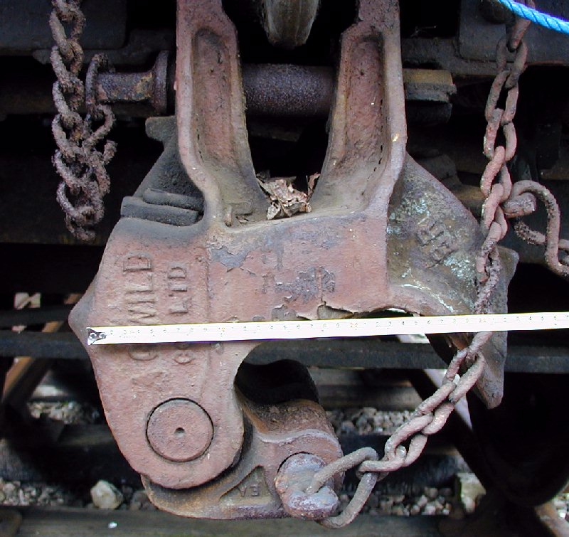
Photo 1. A dropped coupler
on an ex-LNER preserved vehicle at the East Anglian
Railway Museum. Note the emergency coupling pin used only on ex-LNER vehicles. |
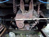 |
Photo 2. Same coupler with tape measure in view
so you can check the size, just about readable when you click on the photo for a larger
view. |
 |
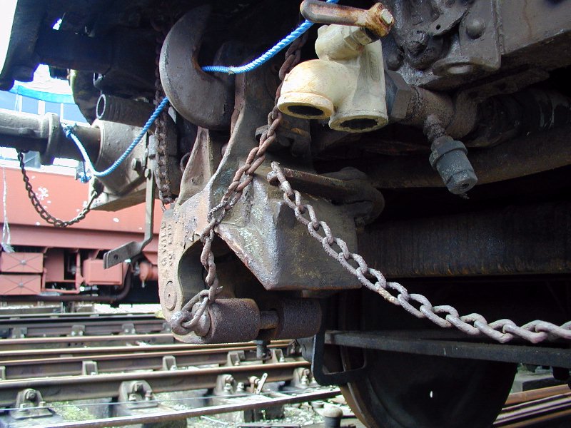
Photo 3. Side on shot makes the relationship to
the drawhook and gangway a bit clearer. |
Table showing equivalent sizes in 00 and H0 for the popular
Kadee couplers.
| Buckeye couplers |
|
|
|
|
|
| 00, EM, P4 |
UK |
AAR-E |
Kadee #5 |
Kadee #58 |
Kadee 711 |
| Dimensions |
drophead |
US* |
x76.2 |
x76.2 |
x76.2 |
| Head width |
14" |
18" |
18.9" |
15.75" |
14.3" |
| Head depth |
10" |
14" |
12" |
12.25" |
10.4" |
| Head length |
13" |
14.5" |
17.4" |
15.75" |
13.5" |
| Headstock to pulling face |
18" |
|
|
|
|
| Headstock to outside |
20.5" |
|
|
|
|
| |
|
|
|
|
|
| H0, P87 |
UK |
AAR-E |
Kadee #5 |
Kadee #58 |
Kadee 711 |
| Dimensions |
drophead |
US* |
x87.1 |
x87.1* |
x87.1 |
| Head width |
14" |
18" |
21.6" |
18" |
16.3" |
| Head depth |
10" |
14" |
13.7" |
14" |
11.8" |
| Head length |
13" |
14.5" |
19.9" |
18" |
15.4" |
| Headstock to pulling face |
18" |
|
|
|
|
| Headstock to outside |
20.5" |
|
|
|
|
| |
|
|
|
|
|
| |
|
* Model Railroader Apr '01 |
INSTRUCTIONS IN THE OPERATION OF
"BUCK-EYE" AUTOMATIC
COUPLERS AND PULLMAN GANGWAYS.
(If you want to get a good
print of the drawing click on it for a higher resolution version).
In dealing with vehicles fitted with "Buck-eye" automatic
couplers and Pullman gangways, the following instructions must be observed. The
following illustration provides a convenient means of reference to the various parts
mentioned in the Instructions:-
*NOTE. In the cases where it is necessary to maintain gangway
connection between coupled vehicles, care must be taken to see that the French pin or
Tower bolt is disengaged before coupling is commenced. The French pin is on the left side
of the gangway sliding door (viewed from outside), and the Tower bolt is on the right side
of the gangway hinged door (viewed from outside). The French pin, when not in use, must be
kept in the receptacle provided.
WARNING.
When coupling together vehicles fitted with automatic couplers,
or coupling vehicles so fitted to an ordinary carriage or engine, staff must not, in any
circumstances, stand between the vehicles, but must wait until the vehicles have been
brought together before passing under the buffers to connect the brake pipes, etc.
1. CHANGING POSITIONS OF MOVABLE BUFFERS.
(a) TO CHANGE THE SIDE BUFFERS FROM THE
"SHORT" TO THE "LONG" POSITION, pull the buffers out as far as they
will come and place the saddles flat on top of the buffer spindles, taking care to see
that the saddle enters the groove of the buffer sleeve and that the opposite end of the
saddle is secured within the three lugs welded to the buffer head or within the groove of
the buffer head as the case may be.
(b) TO CHANGE THE SIDE BUFFERS FROM THE "LONG" TO
THE "SHORT" POSITION, remove the saddles, push the buffers back as far as they
will go and hang the saddles on the hooks provided for them on the headstocks.
2. COUPLING INSTRUCTIONS.
(a) WHEN THE VEHICLES TO BE COUPLED TOGETHER ARE BOTH FITTED
WITH THE AUTOMATIC COUPLER, the procedure is as follows:-
The gangway shields must be off and the buffers in the "short" position.
Each coupler head must be secured in the position shown in the illustration by withdrawing
the support pin, lifting the coupler head as high as it will go, and replacing the
support pin.
The support pin must be inserted in its socket so that the flat side of the head correctly
registers with the locking stop on the body of the coupler. Only when inserted in
this way can the support pin be fully pushed home, thus enabling the TAIL PIECE of
the pin to fall downwards; the utmost care must be taken to ensure that this has been
achieved.
The knuckle of the coupler head of ONE of the vehicles must then be opened by pulling the
uncoupling chain which operates the lock.
The knuckle of the coupler of the OTHER vehicle should be kept closed, EXCEPT WHEN THE
COUPLING IS DONE ON A CURVE, in which case it may be necessary to open the knuckle of both
couplers.
Automatic couplers may NOT engage on ACUTE curves.
The stationary vehicle must have its brake hard on or be prevented otherwise from moving.
The vehicle to be attached should be brought up steadily against the stationary vehicle
and pressed against it without shock, until the gangways are compressed sufficiently
to allow the coupler knuckle to close and the lock to drop.
Staff must satisfy themselves that the couplers have engaged properly by looking or
feeling underneath to make certain that the vertical lock on each coupler is
projecting below the coupler head and that the knuckles of the coupler are clasping
each other. A test must then be made by a slight pull from the engine.
BEFORE COUPLING THE VEHICLES, STAFF MUST SATISFY THEMSELVES THAT THE TAIL PIECE OF THE
SUPPORT PIN IS IN THE PROPER POSITION, I.E., DOWNWARDS.
The carriage warming pipe (when necessary), the bell and lighting cables and the automatic
brake pipe must then be connected, in that order. The gangway curtains (or wind
guards) must be fastened in position.
(b) WHEN COUPLING A VEHICLE OR ENGINE
FITTED WITH SCREW COUPLINGS TO A VEHICLE FITTED WITH AUTOMATIC COUPLERS, first place the
buffers of the vehicle which is fitted with the automatic couplers in the "long"
position, then slightly lift the coupler head, withdraw the coupler support pin, lower the
coupler head and replace the support pin in the coupler head, taking care to see that the
tail-piece of the support pin is turned properly backwards. Place the screw coupling
shackle on the "Buck-eye" hook and screw up in the usual way.
3. UNCOUPLING INSTRUCTIONS.
Before uncoupling two vehicles fitted with automatic couplers,
the gangway curtains (or wind guards) must be unhooked from the eye bracket on the doorway
pillar of the opposite vehicle, and hooked back on the eye bracket of the vehicle to which
it is secured. In some cases, the wind guards. will retract into the roller casing. The
brake and heating pipes, also the bell and electric cables, must also be uncoupled, and
all uncoupled brake pipes placed on the stop plugs.
The Driver should then be signalled to create vacuum and set back slightly, and the
uncoupling chain firmly pulled and held. This will release the lock and allow the knuckle
to open when the engine draws ahead.
After the coupling has been disengaged, the vehicles should be drawn a few yards apart,
sufficiently clear to allow of a safe working margin. When the necessary gap between the
vehicles has been made, the Shunter must exhibit a hand danger signal to the Driver to
indicate that he wishes to proceed between the vehicles and he must obtain an
acknowledgment of this hand signal, working in close co-operation with the Driver before
going between the vehicles.
If, in the operation of dividing, there is any easing backwards or forwards and the
vehicles come together again, no attempt must be made to prevent the "Buck-eye"
couplers from re-engaging, and the train must again be divided.
4. GENERAL INSTRUCTIONS.
(a) The vehicles must not be fly-shunted, and they must
not be allowed to collide with each other or with buffer stops, as damage to the
gangway may result.
(b) WHEN VEHICLES FITTED WITH AUTOMATIC COUPLERS ARE
BEING SHUNTED AGAINST STOCK FITTED WITH SCREW COUPLINGS. OR AGAINST BUFFER STOPS, OR ARE
LEFT IN A POSITION WHERE STOCK FITTED WITH SCREW COUPLINGS COULD BE SHUNTED AGA1NST THEM,
THE SADDLES MUST BE ON THE BUFFERS. AND THE COUPLER HEAD IN THE "DOWN" POSITION.
THE PERSON LEAVING THE STOCK IN SUCH A POSITION MUST SEE THAT THlS INSTRUCTION IS CARRIED
OUT.
(c) WHEN A VEHICLE FITTED WITH AUTOMATIC COUPLERS
BECOMES THE REAR VEHICLE OF A TRAIN, THE SADDLES MUST BE PLACED ON THE REAR BUFFERS. AND
THE REAR COUPLER HEAD MUST BE IN THE "DOWN" POSITION.
(d) In cases where vehicles fitted with automatic
couplers are being shunted for connecting purposes to a vehicle similarly fitted the
saddles must be off the buffers, and the coupler heads in the "up" position.
(e) In the event of a buffer sticking on a vehicle
fitted with automatic couplers, or the couplers failing, the Carriage Examiner's
attention should be called immediately to the matter. All
cases of difficulty must be reported to the first available representative of the Carriage
and Wagon Department.
(f) In all cases where the coupler heads are in the
"down" position, the coupler knuckle should be closed and its support pin fitted
in the coupler head with its tail piece turned.
5. EMERGENCY SCREW AND EMERGENCY LINK COUPLINGS.
An emergency screw coupling with two "D" shackles of equal length is
carried in the guards compartment of all brake vehicles fitted with automatic
"Buck-eye" couplers. In addition ex L.N.E. stock carry an emergency screw
coupling fitted with one short and one long "D" shackle.
On ex L.N.E. vehicles, an emergency link coupling is also carried on the headstock at one
end of all the vehicles fitted with automatic "Buck-eye'' couplers.
Ex S.R. and B.R. standard vehicles do not carry an emergency link coupling.
When, from any cause, the "Buck-eye" couplers cannot be used, the emergency
SCREW coupling must be used whenever possible and screwed up tightly.
If two ex L.N.E. vehicles are involved, the use of the gangways can be maintained. If any
other type of vehicles is involved, the gangway doors must be locked and, in the case of
B.R. or ex S.R.vehicles, the French pin or Tower bolt used (No. 16 and No. 17 on
illustration). IN THE EVENT OF TWO VEHICLES OR VEHICLE AND ENGINE FITTED WITH THE
"BUCK-EYE" COUPLER BECOMING UNCOUPLED, ON NO ACCOUNT MUST ANY ATTEMPT BE MADE TO
COUPLE UP AGAIN WITH THE "BUCK-EYE" COUPLER.
When the emergency screw coupling is used due to mishaps as detailed below, the station
where it is put on the vehicle must advise by the most expeditious means the destination
station where the defective vehicle will be taken out of the train and the staff at the
latter point must replace the emergency screw coupling in the brake conipariment, or on
the headstock of the vehicle to which it belongs.
When the emergency link coupling is used, the defective vehicle should be detached at the
first available station where the emergency link coupling should be replaced on the
headstock of the vehicle.
METHOD OF USING EMERGENCY COUPLINGS
Defect |
Vehicles to be joined |
Emergency coupling to be used |
Method of coupling |
| One or both couplers defective and draw-hook broken. |
One ex L.N.E. and any other vehicle fitted with
"Buck-eye" couplers. |
Ex L.N.E. LINK coupling (to withdraw vehicle with broken hook from
train). |
If sufficient hook is left on the vehicle with the broken draw-hook to hold the
coupler in the "Up" position, leave the vehicle with coupler in that position
and carry out the following operations:-
EXTEND SIDE BUFFERS ON BOTH VEHICLES.
Place the oval end of the emergency link coupling on the sound draw-hook. Place the flat
end of emergency link into the slot of vehicle with the broken drawhook (the slot referred
to is shown by Figure 4 on the illustration). The hole in the flat link must be in line
with the hole which runs through the coupler knuckle and, when the emergency coupling pin
(No. 3 on illustration) is inserted through this hole, the operation of joining the two
vehicles is then complete.
LOCK THE GANGWAY DOORS ON EACH VEHICLE and, in the case of ex S.R. and B.R. vehicles, use
French pin (No. 16 on illustration) or Tower bolt (No. 17 on illustration).
If there is not sufficient hook left to support coupler head, it must hang on link
coupling. |
| One or both couplers defective and draw-hook broken. |
Two ex S.R. or B.R. vehicles or one ex S.R. and one B.R. vehicle
fitted with "Buck-eye" couplers. |
- |
Drop couplers.
EXTEND SIDE BUFFERS ON BOTH VEHICLES.
LOCK GANGWAY DOORS OF EACH VEHICLE and use French pin (No. 16 on illustration) or Tower
bolt (No. 17 on illustration).
Withdraw from service. |
| Drawbook broken on "Buck-eye" vehicle. |
One ex L.N.E, vehicle fitted with "Buck-eye" coupler and
one with ordinary screw coupling. |
Ex L.N.E. LINK coupling (to withdraw vehicle with broken hook
from train). |
If sufficient hook is left on "Buck-eye" vehicle to support
coupler-head, fix latter in "Up" position. Retain side buffers on
"Buck-eye" vehicle in extended position and place the oval end of emergency link
coupling on the draw-hook of the ordinary vehicle.
Place the flat end of the emergency link into the slot of the vehicle with the broken
drawhook. (The slot referred to is shown by Figure 4 on the illustration). The hole in the
flat link must be in line with the hole which runs through the coupler knuckle and when
the emergency coupling pin (No 3 on illustration) is inserted through this hole, the
operation of joining the two vehicles is then complete.
LOCK THE GANGWAY DOORS ON EACH VEHICLE.
If there is not sufficient hook left to support coupler head, it must hang on link
coupling. |
| Drawbook broken on "Buck-eye" vehicle. |
One ex SR. or BR. vehicle fitted with "Buck-eye" coupler
and vehicle fitted with ordinary screw. coupling. |
- |
LOCK GANGWAY DOORS OF EACH VEHICLE, and use
French pin (No.16 on illustration) or Tower bolt (No.17 on illustration).
SIDE BUFFERS ON "BUCK-EYE" VEHICLE to be in extended position.
Withdraw from service.
|
Defect |
Vehicles to be joined |
Emergency coupling to be used |
Method of coupling |
| One or both couplers or support pin defective, |
Any two B.R. or ex S.R vehicles or one B.R. or ex S.R. and an ex
L.N.E. vehicle fitted with "Buck-eye" couplers. |
BR. emergency screw. |
Drop couplers. - EXTEND SIDE BUFFERS ON BOTH VEHICLES, place one
link of screw couplings on one hook first and the other link on opposite hook, and screw
up as tightly as possible.
LOCK GANGWAY DOORS ON BOTH VEHICLES and use French pin (No.16) or Tower bolt
(No.17) on ex S.R. and B.R. vehicles. |
- do.- |
Two ex L.N.E. vehicles fitted with "Buck-eye" couplers. |
Ex L.N.E, screw with short "D" shackle. |
Drop couplers, EXTEND SIDE BUFFERS ON ONE VEHICLE ONLY, place
short link of screw coupl-
ing on one hook first, then long link on opposite hook and screw up as tightly as possible
to retain use of gangway. |
| Broken Inner Drawbar. |
All types of vehicles
fitted with "Buck-eye" couplers. |
- |
EXTEND SIDE BUFFERS at end of vehicle with broken drawbar. LOCK
THE GANGWAY DOORS ON BOTH VEHICLES and, in the case of ex S.R.
and B.R. vehicles, use French pin (No.16) or Tower bolt (No.17).
Withdrawn from service by means of "Buck-eye" coupler or Emergency Screw
Coupling at opposite end of vehicle. |
| Broken Pivot Pin. |
Any two B.R. or ex S.R. vehicles or one B.R. or
ex S.R. vehicle and an ex L.N.E. vehicle fitted with Buck-eve" couplers. |
B.R. emergency screw. |
Remove coupler from vehicle with broken pin and drop the coupler
of the adjacent vehicle.EXTEND SIDE BUFFERS ON BOTH VEHICLES, place one link of screw
coupling on one hook first, then other link on opposite hook, and screw up as
tightly as possible.
LOCK GANGWAY DOORS ON BOTH VEHICLES, and use French pin (No.16) or Tower bolt (No.
17) on ex S.R. or B.R. Vehicles. |
| Broken Pivot Pin |
Any two ex L.N.E. vehicles fitted with "Buck-eye"
couplers. |
|
Remove coupler from vehicle with broken pin and drop the coupler
of the adjacent vehicle, EXTEND BUFFERS ON ONE VEHICLE ONLY, place short link of
screw coupling on hook first, then long link on opposite hook, and screw up as tightly as
possible to retain use of gangways |
| Broken or defective screw coupling on ordinary vehicle, |
Any B.R. or ex S.R. vehicle fitted with "Buck-eye"
coupler and one with ordinary screw coupling. |
B.R. emergency screw. |
LOCK THE GANGWAY DOORS ON BOTH VEHICLES, if both are gangway
fitted and, in the case of ex S.R. or B.R. vehicles, use French pin (No. 16) or
Tower bolt (No. 17), RETAIN SIDE
BUFFERS ON "BUCK-EYE" VEHICLE, in extended position.
Place one link of SCREW coupling on one hook first, then other link on opposite hook,
screw up as tightly as possible. |
| Broken or defective screw coupling on ordinary vehicle, |
Any ex L.N.E. vehicle fitted with "Buck-eye" coupler and
one with ordinary screw coupling. |
Ex L.N.E. emergency screw with short "D" shackle. |
SHORTEN SIDE BUFFERS ON "BUCK-EYE" VEHICLE, place short
link of screw coupling on first, then long link on opposite hook, screw up as tightly as
possible. |
6. AUTOMATIC COUPLERS SEPARATING
If automatic couplers become divided in service, they must be kept as far as
possible in the condition in which they are found, so as to assist in the discovery of any
defect.
Copyright Keith Norgrove.
Last revised: August 27, 2003