| MODEL RAILWAYS | SEPTEMBER 1972 |
THE MODEL RAILWAY STUDY GROUP* REPORTS ON
Carriage & Wagon Suspension - FIXED AXLEGUARD SUSPENSIONS *
*J. S. BROOK-SMITH, M. S. CROSS, |
|
| MODEL RAILWAYS | SEPTEMBER 1972 |
THE MODEL RAILWAY STUDY GROUP* REPORTS ON
Carriage & Wagon Suspension - FIXED AXLEGUARD SUSPENSIONS *
*J. S. BROOK-SMITH, M. S. CROSS, |
|
Although prototype derailments are hardly rare, they are
usually caused by human or mechanical failures, rather than by any inherent defect in the
wheels or rails themselves. We must therefore accept that railway vehicles are eminently
roadworthy.
The prime factor in keeping railway vehicles on the track is the interaction of the wheel
tread and flange with the running surface of the rail. The contours of these components
have to be kept within certain tolerances; wheel contours are re-formed through turning
when the wear has reached certain limits and this ensures that the rail head wears to much
the same shape. Should rails wear unevenly, as they tend to do on sharp curves, they are
replaced.
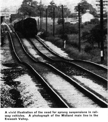
Track is generally well-maintained and for high-speed running it has
to be in near-perfect condition. Nevertheless, there are surprising variations in rail
levels to be found from time to time, usually at turnouts and crossings (where there is
high stress over short lengths of rail) and where the subsoil is unstable.
If a prototype train were fitted with wheels mounted rigidly to the frames it would tend
to derail, simply as a result of these rail level variations. In addition to this factor,
there is the quality of ride to be considered. The stiffness of the baulk road was enough
to disintegrate the admittedly primitive running gear of the original Great Western
Railway vehicles and to cause Brunel to relay his entire line with more flexible track.
With modern weights of hundreds of tons, travelling at up to a hundred miles per hour, it
is no surprise that each and every wheel is mounted in a manner allowing generous vertical
travel under the control of large springs.
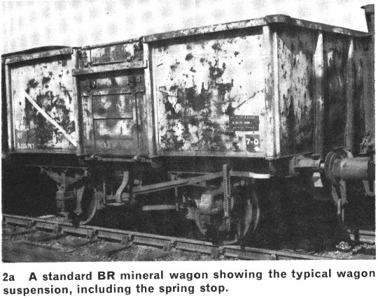
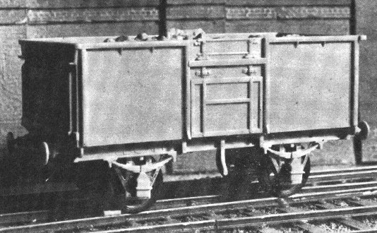
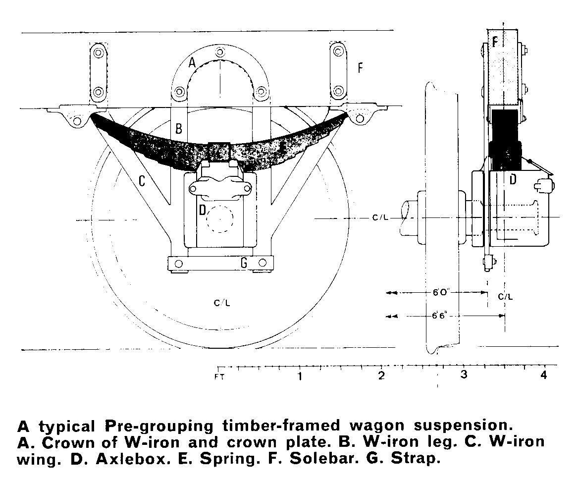
Before the introduction of bogies, both carriages and wagons were fitted with W-irons
mounted directly to the underframes, a system still used for BR's mineral wagons. Typical
axleguards were formed from a pair of legs and wings, usually of 3/4in. plate, bolted
firmly to the inside face of the solebar. There were a very few examples in which W-irons
were attached to the outside face of the solebar, notably in certain L.N.W.R. carriages.
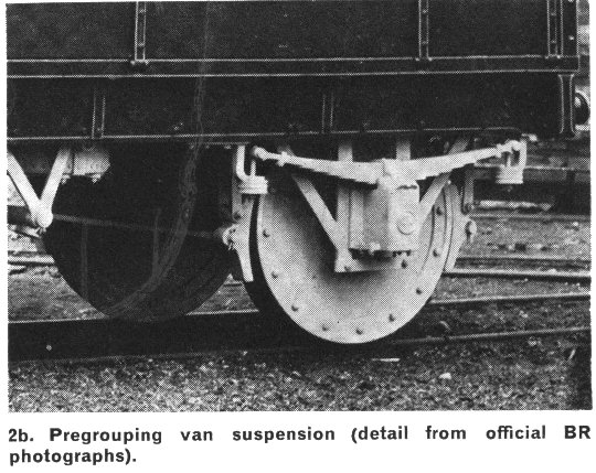
The W-iron legs were usually set 9 in. apart to form slides for the motion of the axlebox.
The axiebox itself was a cast unit containing the semicircular bearing, lubrication wicks
and space for the lubricant. The sides of the axlebox were formed to fit over the W-iron
legs, thus leaving it free to move vertically in the legs, but restricting its lateral
movement and keeping the box upright.
Control of the axlebox movement was effected by means of a multi-leaf spring, resting in a
cradle on the top of the axlebox. The ends of the spring were retained in rubbing plate
fixtures attached to the base of the solebar. Springs and axleboxes were retained in the
axleguards by means of a strap attached across the ends of the legs. In vehicles run in
passenger trains the strap was extended across all the W-irons on each side of the
vehicle, to give the units stiffness and to distribute braking stresses. Passenger stock
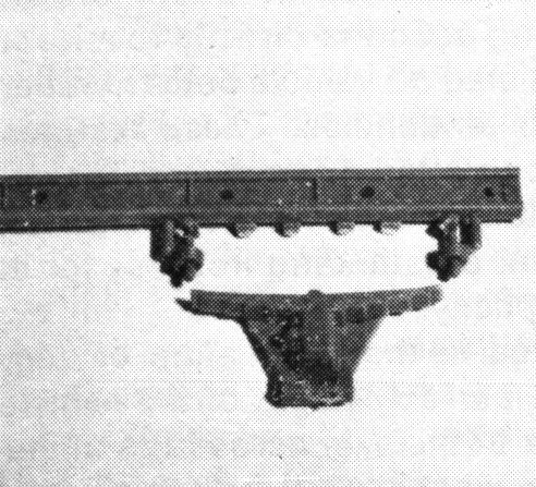
springs were usually held at their ends in stirrups fitted with rubber pads, the stirrups
being suspended from J-hangers attached to the solebars.
|
|
The standard length of spring for mineral wagons fitted with 3ft 1� in. dia wheels was 3ft 6in. Vans with 3ft 7� in. dia. wheels carried springs 4ft 6in. or more long, while some passenger carriages used springs up to 8ft 0in. long. Coil springs were rarely used for suspensions in British vehicles. Spring and axlebox travel under running conditions was of the order of several inches, giving vehicles the ability to negotiate quite remarkable rail level variations when necessary.
The standard distance between the centres of the axle journals of standard gauge rolling stock was 6ft 6in. This is a most important dimension because the axlebox bearings, springs and solebars were set vertically over the journals, and therefore the centrelines of these components were also automatically 6ft 6in. Given typical timber solebars 5in. in width, the resulting dimension between inside faces of the solebars was 6ft 1in. and washers between the W-iron and the solebar would result in a W-iron centreline dimension of 6ft 0in.
When timber solebars gradually became replaced by steel channel for underframe construction, a discrepancy occurred owing to the narrower 3in. flange of the steel section. This gave a between-solebar dimension of 6ft 3in. as opposed to 6ft 1in., and consequently, the W-irons were given an inwards joggle of 1 inch to preserve the old 6ft 0in. alignment. Later still, the 1923 R.C.H. wagons were given an offset timber solebar, so that both steel and wooden solebars were 6 ft 3 in. apart. This arrangement preserved the clearances for self-contained buffing springs which were increasingly used in place of the large all-across springs. The standard 6ft 0in. W-iron setting could not be altered however, and so both steel and timber underframe R.C.H. wagons used joggled W-irons.
The same basic form of W-iron was used for both 3ft 1� in. and 3ft 7� in. wheels, but of course the buffer centreline remained a standard 3ft 5in. - 3ft 6in. above rail tops. The centreline of the axle would thus be 3in. closer to the solebar with the larger diameter wheels, and to accommodate this height differential the solebars of passenger stock vehicles were often shallower than the standard wagon type, with the buffers mounted lower on the headstocks. This factor also accounted for the very slight camber of passenger vehicle springs, as opposed to the wagon springs. Later, wagons were fitted with spring stops mounted on the base of the solebars, to prevent wheel tyres rubbing on the wagon floor in the event of spring breakage.
Early axleboxes were grease lubricated, but oil rapidly replaced grease for passenger and other fast or heavy stock from the eighties onward. Grease boxes could be found on privately owned vehicles until nationalisation, however, to the constant irritation of the traffic officers owing to their propensity for running hot if not regularly refilled with fresh lubricant. (Grease boxes and traffic officers alike, perhaps?). The introduction of tippler mineral discharge systems led to the use of unspillable axleboxes which could be inverted with the wagon without losing the lubricant, and these came to be the most commonly found type of box in recent times.
Such careful provision for springing in vehicles which otherwise were no more than glorified wooden crates emphasises the overriding importance of correct suspension to railway operation. It is therefore all the more remarkable that in modelling the railways the crude, basically incorrect fixed suspension originally found on late Victorian tinplate toys should have persisted in this country, unaltered in principle and virtually unchallenged, to the present day. That this form of suspension has led to countless derailments and untold dissatisfaction in the hobby is beyond question; it is also undeniably the prime factor in the continued acceptance of overscale wheel contours and the distorted dimensioning and mediocre running which of necessity accompanies them.
There is, of course, an explanation for this situation, for every commercial attempt at scale springing has proved at least a disappointment. The reasons for this are not hard to find.
The loading of a prototype wagon spring varies greatly over a short travel, and this balance in resilience is almost impossible to duplicate in model form. Weights and spring harmonics are also in different proportion; add to these the unprototypical model curvature and speeds and the problems are obvious. Even if, somehow, the correct ratios were achieved, one visit from a friendly neighbourhood finger would be enough to remove the operation to square one .
In the early fifties the firm of S & B produced a cast metal W-iron, and a cast spring-plus-box which worked in it under the control of a fine wire spring. Excessive component friction and the difficulty of setting the spring tension correctly no doubt limited the popularity of this system. In 1954 was it really eighteen years ago? Peco brought out the first Wonderful Wagons with plastic boxes and springs working in stamped metal W-irons. Although a vast improvement over the general products of the period, the system proved less than perfect owing to friction and to the characteristics of the materials used in the components. Airfix came very near to producing ideal vehicles, but shied away from springing, leaving instead a vertical slot in the W-iron in which, in theory, the end of the axle could ride to follow rail depressions. Unfortunately the system was mechanically unsound, as pressure on the opposite side of the vehicle tended to counteract the axle movement. This appears to have been the point at which the manufacturers gave up trying and leaned back on their oversized wheels.
|
|
||
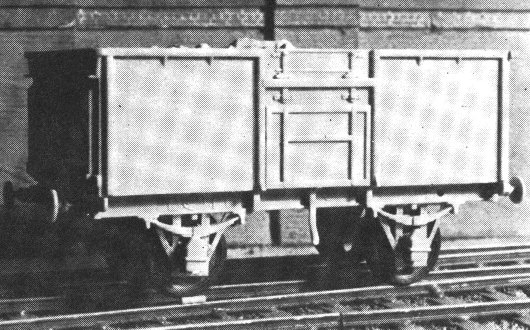
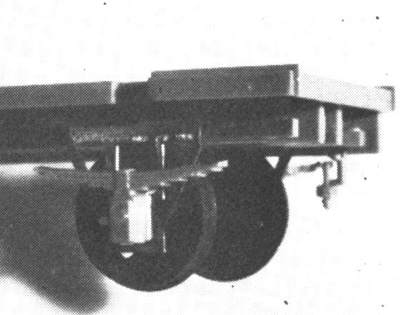
| Top row: Two photographs showing the action of compensated suspension as a BR standard wagon model negotiates an obstruction placed on the rail. Note the action of the right-hand axlebox, which is attached to the suspension unit independently of the spring moulding. With the equivalent of a standard brick on the line, all wheels remain in contact with the rail. | |||
|
|
||
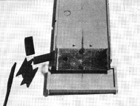
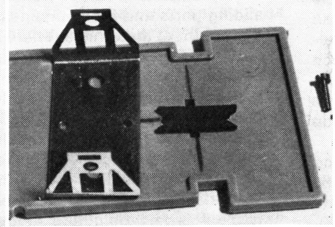
| Second row: Strip rubber prepared for use as packing. The vees cut out of the ends of the packing enable it to centre about the fixing screws. This prevents the packing becoming displaced in use. Owing to the recessed floor of the Airfix vehicle two packing strips are necessary instead of the usual single strip. The left-hand photograph shows the strips and a suspension unit in position. The right-hand photograph shows the units and the flanged bearings before assembly. | |||
|
|
||
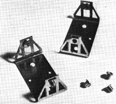
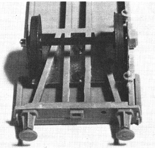
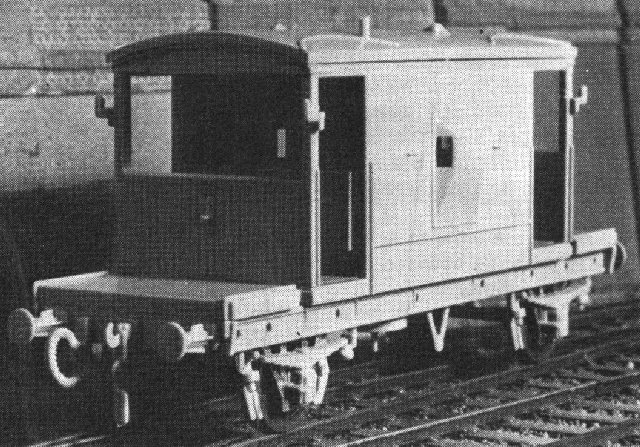
| Third row: Underframe timbers in position over the unit; wheels in place and one solebar mounted. The right-hand axlebox and spring moulding are already attached to the W-iron. The right-hand photograph shows the vehicle, an Airfix Brake Van, fitted with fully compensated suspension, clasp brakes, and springs and axleboxes moving with the axleguard independently of the underframe and suspension J-hangers. | |||
 |
|
|
|
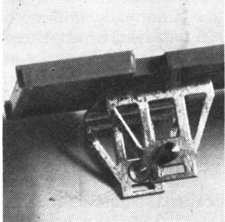
| Bottom row: Details from the Brake Van construction. L to R: Spring and axlebox moulding separated from the solebar, leaving the J-hangers in position. The W-iron moulding is carefully detached from the solebar and from the axlebox and spring, and the surfaces sanded flush. The floor unit ready drilled and tapped 12 BA, with the rubber packing strip positioned ready to receive the suspension unit. The unit in position, the settings adjusted, the screws cut flush with the top of the floor and given a touch of locking compound. The spring and axlebox moulding in place on the W-iron with the opposite solebar already in position. | |||
When the M.R.S.G. designed Protofour around correctly scaled wheel and rail contours it was clear that track would have to be very well laid or model suspensions would have to be flexible - preferably both. As the former requirement was easily achieved through the use of the new constructional techniques, initial suspensions were designed to enable commercial vehicles to be run on Protofour layouts.
The requirements of a successful suspension system are:
1. Axle/bearing friction to be minimal.
2. Axle alignment in underframe to be accurate.
3. Prototypical appearance.
4. Wheels to remain in contact with the rail at all times.
As most commercial axleguards already contained an axle hole, it was a simple matter to provide a small bearing which could be fitted into them. This bearing incorporated a flange which prevented it from entering the axle hole beyond a standard depth, and also a coned bearing surface, to accept the standard axle end points. These latter were set at 26 mm, the equivalent of the prototypical journal centres. The advantages of this system were the simplicity of conversion of stock, the free running of the wheels, the minimal maintenance and the ability to spring wheel sets out of the axleguards, which could not have been done with axles of prototypical length.
The running of these wheel sets in the bearings was so good that a minor problem arose; stock could not be kept in sidings unless there was a negative slope, as otherwise the vehicles tended to take off of their own accord! To achieve the correct bearing settings in the typical commercial vehicle with its over-scale W-irons and guesswork spacings could prove time-consuming, however, and this led to the development of a preformed axleguard unit which would accept the wheel sets at the correct settings automatically and which could then be fitted to the vehicles as a self-contained suspension unit.
This unit was produced as a U-pressing of scale thickness, the arms of which were formed as scale W-irons. Pre-punched 2.0 mm dia. holes accepted the standard flanged bearings as a press fit and wheels of up to 3ft 8in. scale diameter could be fitted. This suspension unit could be fitted directly to new vehicles, and to commercial vehicles also, once their axleguard mouldings had been removed. Spring and axlebox mouldings salvaged from the commercial vehicles could be fitted over the projecting bearing as decoration. The suspension units solved the first three M.R.S.G. requirements in the simplest possible way.
In fitting the units to scale vehicles, it was necessary to use packing material between the unit and the floor to compensate for the variations in height which resulted from the several combinations of wheel diameter, solebar depth and buffer positioning. The units contained two 1.3 mm dia holes on the centreline which enabled them to be fitted to the packing or the floor using standard track rivets. From this feature there originated two developments of great importance. The first is compensated suspension, and the second is sound insulation.
The variation in rail levels over the wheelbase of a vehicle running on reasonably well-laid track is normally no more than 0.5mm, requiring no more than 0.25mm relative wheel movement to the underframe to compensate for it. Because such small movements can hardly be detected by eye, and because axlebox and spring mouldings add to the deception, it is possible to allow the axleguard unit to move in the underframe to provide the compensating action.
This is achieved by fitting a narrow packing strip and setting the rivets loosely. The axleguard unit will then rock slightly about the vehicle centreline, and because the outside dimension of the unit is 24.00 mm, equivalent to 6ft 0in, there is just sufficient room for this movement in a scale underframe.
If a hard material such as Plastikard is used as packing, there is a transmission of running noise to the vehicle body; not so much as in a typical commercial vehicle where the axle is effectively running in a part of the body, but an unpleasantly high level nonetheless. Through the use of a thin felt packing, this noise transmission is virtually eliminated, and a slight degree of resilence is obtained into the bargain. The best packing material is synthetic rubber, however, which must be in the form of replaceable strips. The resilence of the rubber enables fine adjustment of the flexibility of the axleguard unit to be carried out, and to this end, the best mounting method is the use of 12BA screws, which are a close fit in the 1.3mm dia. holes. These may be adjusted until the axleguard unit sits vertically and has an easy but controlled compensating action. The threads are then sealed with locking compound to preserve the settings. Whenever necessary, the units may be removed and replaced without damage to the vehicle.
The fourth M.R.S.G. requirement was met through the use of this
suspension method, and in addition the following advantages were obtained:
5. Simple maintenance - minimal moving parts.
6. Accessibility - wheels or units removable at any time.
7. Adaptability - units may be mounted in many different ways.
8. Minimal expense.
The last point is best illustrated by the fact that the ideal packing strip is model aeroplane motor elastic, a single packet of which will provide packings for the accumulated vehicles of several large layouts!
To standardise procedure, the use of this strip is recommended as the units then all have precisely the same degree of resilence and flexibility. To accommodate the variations in packing thickness required for different vehicles, the bridge of the suspension unit is given a shallow Vee form, the amount being adjusted to give the correct rail-to-buffer height when the vehicle is placed on the track.
As may be seen from the illustrations, the compensated suspension unit is ideal in its application to the great majority of vehicles. It may be adjusted to give correct height of the buffer; spaced for any desired wheelbase; decorated with scale axleboxes of the correct type, and given springs of correct form. It may also be given clasp-type brake shoes which consequently remain at constant settings in relation to the wheels; joined to adjacent units by a scale strap extension without affecting its performance, and a scale underframe timbering added without detracting from its operational effectiveness.
Typical of its adaptability are the several treatments of the spring and axiebox mounting. The standard bearing projects from the suspension unit, and either an axlebox, or an axlebox complete with spring, may be mounted on the unit using the original axlebox hole as a location point. The spring and box will both move with the unit in the latter case. If, however, the axlebox only, with a channel cut into the top surface, is mounted on the unit, and the scale spring fitted directly to the solebar, movement of the unit will cause the axlebox to move relative to the spring, giving a most convincing impression. Alternatively, the spring rubbing plates may be mounted on the solebar, and the axlebox and spring mounted on the unit. The ends of the spring are cropped sufficiently to allow them to move vertically between the rubbing plates. This is even more effective in giving the impression of working springs.
The overriding advantage of this system compared to others is its complete freedom from interface friction. There are no sliding parts and the compensating action is directly relative to the weight of the vehicle. There is also no vehicle body vibration as the rubber damps down such tendencies. These features, combined with the silence of operation - one hears the rail joint clicks very clearly - offer a totally new concept and standard of model railway vehicle operation, outstanding not only for its effectiveness but also for its simplicity.
Two factors must be considered in the installation of compensated suspension. One is the correct weight of the vehicle, the other is the correct alignment of the axle across the underframe. It is very difficult to suggest what is a correct weight for a model vehicle as this depends to a large extent upon the conditions of the individual layout. All that can be given are limits within which the correct weight should fall. The vehicle should be sufficiently heavy to prevent bounce when travelling over misaligned rails at normal running speed, and not so heavy that the quality of running is affected by the distortion of the axleguard owing to the coning of the bearing. This is a wide spectrum! The second problem is solved through the use of a drilling template which will position the 12BA tapping holes (1mm or No. 61 drill) accurately on the vehicle centreline.
There are, unfortunately, always exceptions to the rule, and certain vehicles will not accept the compensated suspension units happily. These are the old open-framed wagons, such as early tank wagons, and well- and machinery wagons, in which the bridge of the unit would be obtrusive. There are solutions to these problems and it is intended to cover them in a subsequent article, together with the problem of the six-wheeled vehicles for which the units are an ideal solution and for which an extremely simple mounting system is possible.
In summary, the introduction of the Protofour compensated suspension units marks a new phase in scale railway modelling. At last the traditional rigid suspension system has been abandoned and a fully-compensating, sound-insulated replaceable suspension accepted as the norm. It must be recorded that this result could not have been achieved without the assistance of a member of the Protofour Society who provided certain essential tooling, thus proving that in Protofour, at least, the individual modeller can have a direct and vital influence upon the hobby.
Copyright - Model Railway Study Group, reproduced with permission.
Back to Magazine Index, Back to Site Index.
K Norgrove 25/04/03