| Model Railway Constructor | November 1968 |
PROTOFOUR --- 11 a new scale modelling standard by a model standards study group J. Brook Smith, M. S. Cross, D. E. Jones |
|
| Model Railway Constructor | November 1968 |
PROTOFOUR --- 11 a new scale modelling standard by a model standards study group J. Brook Smith, M. S. Cross, D. E. Jones |
|
Template jigs
PART 10 of the Protofour series described the uses of templates in the planning and construction of model railways. The advent of templates brings with it a considerable improvement in methods of track construction, and this article describes the building of track using a Protofour template as a jig.
Track performance. as we have seen, is determined by five basic factors, and additionally by the vertical and longitudinal alignment of the rails. In the Protofour system, the basic factors are controlled by the wheel and rail contours, and by a set of four gauges, TG, CG, CF, and BB. The longitudinal alignment of the rails is facilitated by the use of templates, but the vertical alignment, the levelling of the rail tops, is another matter altogether. In the "good old days" when a row of tacks was slammed into the baseboard to provide a rail foundation, level rail tops fell into the category of miracles; nowadays the outcome is largely determined by the precision of the components. Protofour components are precise; the finely finished pre-punched sleepers and the specially made rivets ensure an even surface to which the rail may be soldered. Unfortunately, another factor can undo all the good work, for if the track is constructed on an uneven surface, the rail tops will be uneven too. This factor alone indicates that the construction of model railway track in a jig is the only thoroughly reliable method, and it is therefore standard Protofour technique. In a jig, all factors are under control, and the modeller has the optimum conditions for producing top quality track.
The mention of jigs conjures a vision of complex and expensive structures beyond the capacity of ordinary mortals to build or operate. Model railway jigs, fortunately, could hardly be less so. All that is required is a hard, flat surface to which a template may be attached, and a small offcut of block or chipboard, with a laminate surface, is ideal. The use of a portable jig of this kind, as opposed to track construction on site, is strongly recommended for the following reasons:
1. It ensures an even standard of track accuracy and finish throughout the layout.
2. It may be placed on a bench or table where sufficient light is available to see exactly what is happening during assembly.
3. It may be manoeuvred into convenient positions for the work in hand, giving greater ease, speed and accuracy of construction.
4. It allows simple and effective adjustment and replacement of components to be carried out.
5. It facilitates the removal of debris without disturbance to the track.
6. It enables the construction to be carried out in comfort, at any convenient time and place.
The laminate-faced board is transformed into a jig by attaching a Protofour template. This is done very quickly and easily by placing double-stick tapes on the work surface, and laying the template over them. The paper template will be immovable during construction, but by peeling the template and tapes together from the jig after use, the latter will be left clean, and ready for the application of the next template. With such a neat and reliable method it is not worth considering the use of liquid adhesives.
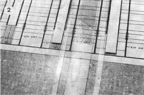
When making plain track, the sleepers are retained in the jig by double-stick tape running along the centre of the template; for turnouts the tapes are laid outside the rail lines. There should naturally be a tape below the template in these positions, and to ensure this, tapes may be applied first to the underside of the template. and the templates and tapes laid together on the jig surface. As the tapes lose their "tack" during use, it is clear that the template would have to be replaced fairly often. To avoid this, and to cancel out the effect of uneven riveting, it is recommended that strips of acetate sheet are laid over the "working" tapes, and further double-stick tapes laid over the sheet. The latter tapes may then be replaced as often as necessary, without disturbing the template itself (photo No.2) The sleepers are thus carried above the face of the jig, and the occasional "wild" rivet cannot affect the rail level.
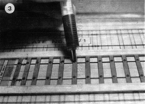
A further Protofour technique is the use of solder paint for the attachment of rails to rivet heads, in preference to traditional soldering methods. As chairs will be applied eventually to the rivet contour, excess solder at the joint is not required; it will be found that solder paint does not tend to "blob" on the rail side. "Fryolux" is mixed thoroughly before use, and stored in a plastic throwaway syringe, without needle. The syringe is charged like a fountain pen, by placing the nozzle in the paint, and withdrawing the plunger - could anything be simpler ? - and is then used to apply the paint evenly to the rivet heads (photo No.3). A hot soldering iron will produce a neat and effective joint. If the paint is found to be too stiff to enter the syringe, it may be thinned by the addition of a very little water. The paint must always be thoroughly mixed before use, and if left in the syringe for long periods the particles tend to settle out, so a new charge should be given before every construction run.
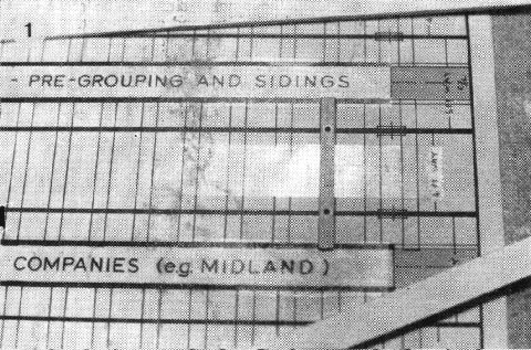
For plain track it is advantageous to place card strips on the template to act as sleeper edge limiters, so that lateral positioning is automatic (photo No.1). This is not essential but it results in a neater track.
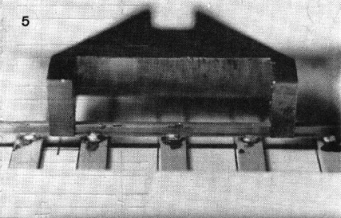
The procedure for plain track is to charge the sleepers with rivets. and set them with the riveting tool. The prepared sleepers are then fed into the jig, in accordance with the sleeper spacings, rivet head upwards. The rivet heads are then charged with solder paint from the syringe (photo No.3). Rail is selected, noting that the deeper head lies uppermost in the finished track (photo No.5). The undersurface only is then cleaned with the glass fibre brush. The track gauge (TG) is used to set the rails upright and to correct spacing, in position over the template guide lines (photo No.4).
|
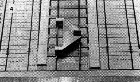
4. Rails in position tor soldering, held upright and to gauge by TG. |
|
5. Solder joints produced by solder paint method. |
|
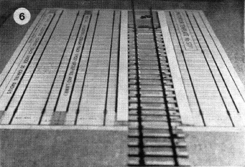
6. Completed track as produced by the multiple jig. |
The rails should be soldered, commencing at each end of one rail. The remaining joints of this rail are then completed using the steel rule as a straight edge. Rail should always be pressed down lightly while soldering, to ensure close contact with the rivet head; if any unevenness is detected, this should be remedied by reheating the joint, exerting downward pressure. The remaining rail is soldered using TG for correct spacing, and the track is then complete. It is removed from the jig by lifting gently from one end.
Continuous lengths of rail may be made by replenishing the jig with sleepers and continuing as before; longer jigs may be made from sections cut from two or more templates. Soldering can be carried out at random using Protofour jigs, as there is sufficient flexibility to accept temperature expansion of the rail without affecting the essential settings.
In summary, the MRSG has provided the means to construct precision track, correctly representing the prototype, without the necessity for the modeller to obtain specialised knowledge; reduced the workbench space to a single piece of wood, about a square foot in area; provided "instant jig" materials that do not even require the use of liquid adhesives, and are completely odourless; reduced the art of soldering to the point where it is no longer necessary to touch solder, and in short, has "housetrained" model railway track construction. The Protofour system has reached the stage where the modeller can produce track within five minutes of laying out the materials, and track that will work faultlessly from the moment it is laid.
The next article in this series will describe turnout construction using Protofour jig techniques.
Materials required for Protofour Track construction:
* Rail, sleepers and Crossing Timbers, Rivets.
* P4 Gauge set, Punch and Rivet tools, Press.
* Soldering iron, Solder paint, Syringe, Glass fibre brush.
* File, End cutters, Square-ended pliers, Steel rule.
* Templates, Jig base, Double stick tape, Nylon pen, Pencil.
* Facial tissues for cleaning.
Copyright - Model Railway Study Group, reproduced with permission.
Back to Magazine Index, Back to Site Index.
K Norgrove 25/04/03