| Model Railway Constructor | April 1969 |
PROTOFOUR --- 12 Templates and turnouts |
a new scale modelling standard by a model standards study group J. Brook Smith, M. S. Cross, Dr. B. Weller |
THE use of templates in the planning and construction of model railways was described in Part 10, and the building of plain track in Part 11 of the Protofour series. The construction of turnouts follows much the same procedure as in plain track, but the several dimensional requirements of turnouts necessitate special techniques.
The overriding advantage of constructing track in a jig is that all the factors affecting track performance are under direct control. In the case of crossings, where the full range of gauges is needed to determine rail settings, the argument for the use of jigs is especially valid. Turnouts, which involve a number of interdependent settings, are consequently the most demanding items of track, and require special care in draughting and assembly.
Protofour turnout construction templates were designed to relieve the modeller of the need to draught his own diagrams, and by indicating all the essential data they take the guesswork out of the construction and virtually guarantee the correct functioning of the unit. They are intended for use in jig form, and as such are most efficient aids to the modeller and ensure the most productive use of modelling time.
Making the jig
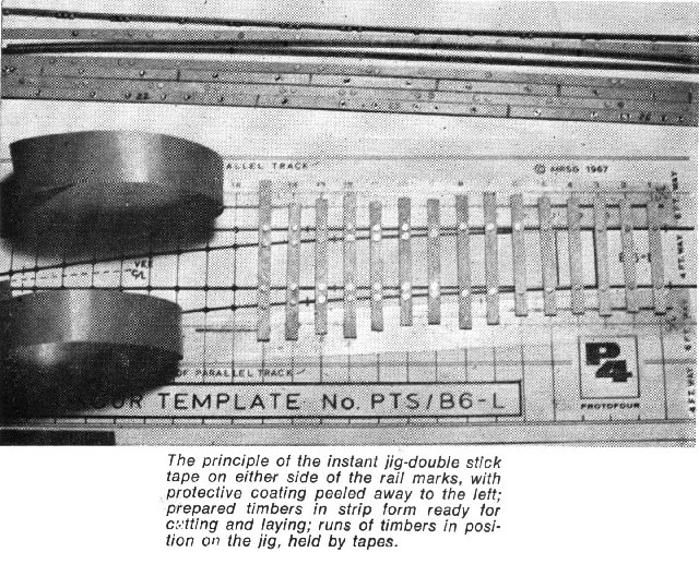
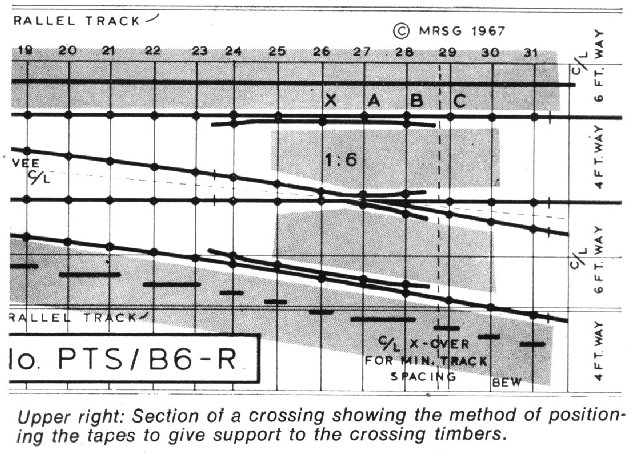
The templates are printed on special paper and are to constant scale and pattern. Consequently, they may be cut and assembled into complex formations and given timbering patterns to choice. They are converted to construction jigs by sticking them to a suitable surface by means of double stick tapes. Such a surface is laminate-faced blockboard, which may be used again and again simply by peeling the template away after use. To convert the jig to a multiple run type, or to provide clearance for rivet bases, thin acetate or Polyglaze strips are laid over the surface tapes and a further replaceable tape layer added.
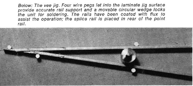
For vee rail assembly it is advisable to provide a miniature jig, which can be made by taping a crossing template of the appropriate value to a laminate board and drilling four holes to accept wire studs. This ensures that the vital alignments of the point and splice rails are maintained and the rails held upright while soldering.
Preparation for construction
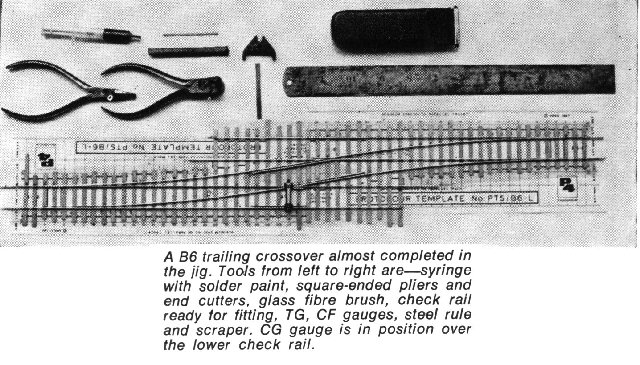
The crossover featured in the accompanying photograph contains some 4yd of rail, l3ft of timber, and over 200 rivets. It is clear that unless construction is efficiently organised, time will be wasted in unnecessary operations. It is also clear that a turnout which fails to operate correctly involves a loss of time, patience and a fair quantity of material. The odds against construction on site, whatever the scale/gauge ratio, in conditions of uncertain lighting, awkward access and unproven surfaces are distinctly unfavourable. Those who insist upon this procedure stand to lose much of the pleasure of scale model railway construction.
The equipment required should be laid out, and the workbench moved to a location where there is proper illumination. Experience suggests that bright daylight is the most satisfactory environment, as all parts of the jig are evenly lit. Bright spotlights and direct sunlight tend to accentuate the shadows and are tiring to the eyes. The effect of light upon the quality of construction is remarkable, and adjustments considered satisfactory in subdued light can often be seen to be wrong the moment they are examined in daylight.
The three gauges, TG (track gauge), CF (crossing flangeway) and CG (check gauge), are, of course, essential, as are the punch and rivet tools. A glass fibre brush is used to clean the rail prior to soldering. A sharp file - always purchase a new one for these operations - square-nosed pliers, end cutters and a scraper are used for working the rail. Soldering is carried out with the assistance of a syringe, which acts as a combined solder paint storage and applicator, or alternatively the syringe may contain flux, with solder used in the usual way. The soldering iron should be of adequate size, the 25W Solon iron having about the minimum capacity. The object of the exercise is to obtain a rapid and even heating of the joint, for which an adequate reserve of heat is essential. Solder paint seems to require a hotter iron than normal solder, and the traditional electric iron would appear to be preferable to the instant heat type, as it offers a more constant heat level. The equipment is completed by a nylon-tipped pen, a pencil and a steel rule.
Timbering
Operations commence with the numbering and marking out of the timbers. The quickest and most economical way to do this is to retain the timber strips in their original lengths, and to mark individual timbers consecutively along them. The strip is laid alongside a timber centreline, and the rivet dots marked opposite their positions on the template. The marks may be made with the nylon pen, which gives an unmistakable indication, but a ballpoint pen or a pencil may be used if preferred. A transverse line, marked over-length, indicates the end of the timber, which will be trimmed to size later. Each timber is given a serial number.
The marked strips are next put through the punch tool and all dots removed. Keeping the marked surface uppermost, the timber holes are pressed over the upturned shanks of the rivets and the charged strip fed through the riveting tool, where all rivets are set. The marked side of the timber thus becomes the undersurface of the unit The entire marking and riveting for an average turnout should take less than 20 minutes.
The timber strips are next cut at the transverse lines using a pair of scissors or modelling knife, and are laid on the jig according to the serial numbers. Care should be taken to align the rivets with the rail lines to allow the fitting of chairs.
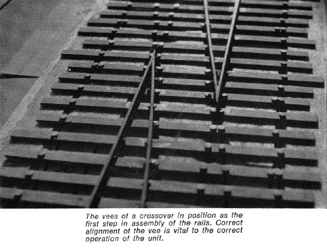
Crossing vee
The efficiency of construction is much increased if batches of rail are prepared beforehand. For crossing vees two rails should be filed as a pair, with opposite "hand", to ensure an exactly similar vee angle in each rail. The procedure for filing switch and vee rails has been described in previous articles in this series.
All rails are set correctly with the deeper running head uppermost, and point rails always lie in the straight, or main road of the turnout. Before setting rails in the jig, they are de-burred using the scraper, and cleaned with the glass fibre brush. After soldering and wiping clean, they should be trimmed once again to remove any excess solder that might affect the running.
The crossing rivets are next given a coating of solder paint, or flux, as appropriate. The vee is eased into position, with the nose over the "A" timber, and the point and splice rails soldered at the outermost rivets. The nose is then adjusted with the greatest care, and soldered. This operation determines the success of the crossing, and must be carried out accurately. The remaining rivets are then soldered in turn.
Stock rails
These are cut to length, the set marked and applied carefully with the square-nosed pliers. The set is very slight the same angle as the switch planing and is applied to the curved road only. The stock rails are then soldered to timbers (1) and (2), using the rail marks as a guide, and the TG to maintain spacing and to hold the rails upright. A single rivet may be lightly tack-soldered to retain the stock rails opposite the crossing.
Switch and wing rails
Each switch, closure and wing unit is made from a single rail; these rails should be prepared beforehand. The toe of the completed switch is set over the first "P" chair, and the knuckle position carefully marked. The wing rail is bent to the appropriate angle, the rail replaced and the wing rail length marked. The wing is then cut. trimmed square with the file, and flared.
Assembly commences with the setting of the straight road knuckle. This is a key setting, complementing the vee. The straight road is aligned by placing a steel rule across the toe and vee, and holding the switch rail against it. The crossing flangeway is set using CF. The knuckle is adjusted until both settings are obtained, whereupon the rail is soldered at the "X" timber. With the basic positioning established, the CF is maintained and the wing rail soldered at the "B" timber. Alignment is then carefully rechecked by looking along the rail and any necessary adjustment carried out. The remaining rivets are soldered using the steel rule to maintain the alignment of the road. The curved switch is then fitted, using the same procedure, with the exception that the steel rule cannot be used for the crossing alignment of the curved road. This has to be achieved by eye, or by a second CF across the gap, or by means of a short, straight edge.
Experience of crossing work soon accustoms the modeller to checking alignments by eye, which is, after all, one of the best tools for the purpose. However, CF must always be used for the flangeway. The time taken over these operations varies considerably with experience, and about thirty minutes is reasonable for a beginner. Although considerable reduction in the time is possible, things should never be rushed, as the settings are of paramount importance to the success of the layout.
Finishing off
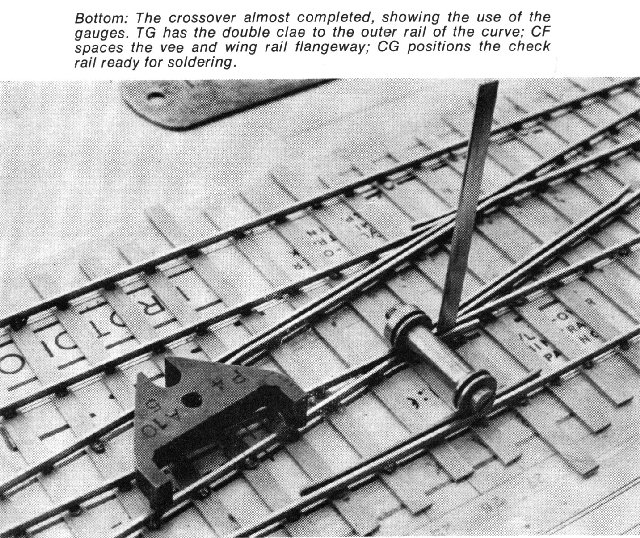
Care should be taken to ensure a snug fit of the switches into the stock rails, which latter are adjusted as necessary, and finally soldered. TG is used to maintain settings of the stock rails while they are soldered, and so the straight and curved alignments will follow the switch rails correctly. The TG should be used with the double claw to the outside rail of the curve, to give correct gauge widening.
Check rails are made from scrap rail, cut to length, filed flat at the ends, and flared. They are set using the CG for correct spacing from the crossing nose.
Sleeper ends are marked by a pencil line according to the desired pre- or post-Grouping length, shown on the template by the outer or inner edge of the solid line.
The unit is now ready to be detached from the jig. Using a table knife, the blade can be slid under the timbers, which are carefully prised away from the tapes, working from one end of the unit to the other. Any unsoldered rivets will be noticed at this stage, and should be remedied immediately. With the unit free from the jig, the crossing timber ends may be trimmed using end cutters, craft knife or scissors, although this operation is not necessary if timbers have been previously cut to size. Care is needed to avoid breakage of the timbers, but in the event of an accident, a new timber can be fitted without difficulty.
The turnout is now ready for weathering, and the fitting of tiebars. cutting of electrical breaks, etc. These subjects will be covered in later articles in the series, subject to the Editor s approval.
General
The use of the jig is by no means finished with the completion of the turnout. The same jig may be used again and again with only the occasional replacement of the surface tapes; each and every turnout will be exactly dimensioned, as its fellow, and interchangeable with others from similar P4 templates. Catch points and individual crossings may be made using sections of the jig. More complex formations can be built using the same constructional methods and the appropriate template. Unusual formations can be constructed by using parts from various templates in combination. As the jig Aworkbench" measures only a foot or so in length, it may be worked on almost anywhere, while a spare template and a few lengths of timber in the briefcase can be used for marking in any ten-minute break. Once the initial outlay of equipment has been covered, the system is most economical; only some five shillings worth of timber and rivets are involved in an ordinary turnout, and two yard lengths of rail. At the rate of a turnout an evening, a P4 layout is only a few weeks away.
The Protofour Society
This Society has now been formed and the inaugural meeting was held on February 5. The aims of the Society are to promote modelling to Protofour standards and to exchange information and ideas relating to the standards. There will be some advantages to be gained for those people who are building Protofour layouts.
The Society will be managed by a Committee from the Model Standards Group - Malcolm Cross, Peter Elsey, J. Brook Smith and Bernard Weller. The day-to-day affairs of the Society will be run by an Executive Committee appointed by the Managing Committee, and the former will also appoint their sub-committees for any particular duties.
The subscription to the new Society is to be 30s 0d per annum, and it is planned that a Society Magazine be issued and Dick Ganderton (of EM Gauge Society Marshalling Yard fame) has been elected to become the Editor.
All queries and requests for further information should be addressed to the Hon. Secretary: K. G. Cottle.
Copyright - Model Railway Study Group, reproduced with permission.
Back to Magazine Index, Back to Site Index.
K Norgrove 25/04/03