| Model Railway Constructor |
May 1967 |
PROTOFOUR ---
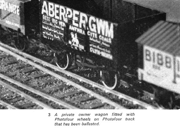
5
a new scale modelling standard
by a model standards study group
J.Brook Smith, M.S.Cross, D.E.Jones
W.L.Kidston, B.Morgan, Dr.B.Weller |
|
THE days when a modeller could slam a row of tacks
into a baseboard and expect to produce scale trackwork thereon are happily passing. The
same is generally true of on site construction on permanent baseboards in ill-lit attics;
accuracy of construction is just not possible in such circumstances. As we noted in part four of the series, track is three-dimensional, and it
must be correctly aligned in three axes:
| Gauge must be correct. |
| The road must be correctly aligned |
| The level of the running rail must remain constant. |
To obtain track which is correctly aligned in all
axes we must construct it in circumstances where these conditions are guaranteed, which
means, in effect, jig building. The advantages of jig building are:
| Level working surface. |
| Correct alignment of sleepers. |
| Manoeuvrability of the working surface. |
| Adequate illumination of the work. |
| Speed, ease and accuracy of construction. |
| Test and adjustment possibilities at all stages of
assembly. |
| Prefabrication of crossings and special layouts. |
| Standardisation of all track on the layout. |
Most modellers take fright at the mention of jigs,
but the sole purpose of a jig is to hold the components in position while they are
assembled, and nothing else. Protofour track can be made to high standards of accuracy in
a jig made from card, assembled without the use of glue, and this demonstrates that
accuracy need not involve expense. As with so many aspects of Protofour, the key to
success is the adoption of correct constructional techniques.
Tools and equipment
The correct tools make light of any operation, and
especially of model railway construction. We do not need many tools, but certain equipment
is essential.
Track components
| Sleepers. Protofour wooden
sleepers, pre-punched at correct rail spacing, to pre- or post-grouping standard lengths. |
| Protofour tinned rivets. |
| 'Kingsway' Bullhead rail - the only
rail suitable for Protofour operations. This rail may, of course, be used with any 4mm
scale system. |
| Chairs. At the time of writing,
Protofour chairs are still under development, but suitable alternative chairs are marketed
by Kingsway. In the Protofour system, the chairs are decorative only. |
| Crossing timbers, scale l2in wide, in
lengths, to be punched and cut to desired configurations. |
| Protofour Ballast- scale 2in mesh. |
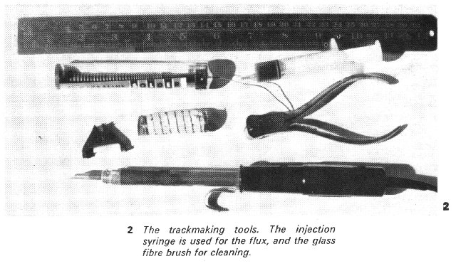
Equipment
| Steel rule, preferably marked in mm and inches. Used
for drawing out jigs, general measurements and for checking straightness of rail. |
| Engineer's square (small), for drawing out jigs and
general checking. |
| Protofour track gauge (3-point type). |
| Protofour riveting and punching tool. |
| Soldering outfit: Solder paint (Fryolux) or 60/40
tin/lead solder, resincore ('Savbit= suggested). Soldering iron, the Solon 25w type is
ideal. Flux, to choice. Disposable injection syringe, obtainable from medical suppliers
for a few pence each. Ideal for application of flux, or for fine oiling. For their general
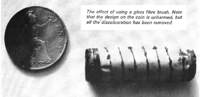
usefulness, several may be bought at a time. Glass Fibre Brush, for cleaning metal prior
to soldering. The industrial type wrapped in tape is more useful to the modeller than the
typist=s pencil form as it may be wrapped with wire and the cleaning action adjusted by
compressing the fibres. |
| Pencil and drawing pen, for marking out. |
| Cutters and file, for working rail. |
| Facial tissues for soldering iron cleaning, removal of
flux, and general dirt. |
| Protective cover for tables and similar working
surfaces soldering irons can be rather destructive. |
| Protofour wheel BTB gauge; crossing flangeway gauge;
Skarsten scraper (small) for finishing rail. |
|
Preparing the jig
The jig should be prepared on a flat surface, and
perhaps an offcut of the track base chipboard, surfaced with hard smooth card, or better
still, a laminate such as Formica, is the most convenient base. The width need be no
greater than twice the width of a sleeper, and the length to suit the length of rail as
purchased.
One edge of the jig should be dead straight, and
this need only be the edge of the card or the laminate. A centre-line is drawn parallel to
this edge, and, equally spaced on each side of the latter, two reference lines are drawn,
19mm apart. These will represent the inside gauge faces of the rails, and serve as a guide
in positioning the rails for soldering.
Once the centre-line and guide lines are drawn, or
scribed on the laminate, we may use the square to mark the spacing of the sleepers. Here
comes a point of interest, as the various companies often varied the spacing of sleepers,
and usually placed sleepers closer together where rail joints occurred. As the rails
themselves varied in length it will be seen that this is another subject to fascinate the
pre-grouping modeller. The LNWR had the longest rails, rolled at Crewe, which were 60ft in
length; by comparison the Midland used 45ft rails, and some of the more impecunious
concerns made do with whatever was available on the market, and these rails might be 30ft
or less. An average figure for sleeper spacing is 2ft 6in between centres, variable
according to the nature of the formation.
The sleeper spacings marked on the jig as single
tines represent the leading edge of the sleeper, so that the latter can be positioned
accurately against the line. They may be centred in the jig by setting a strip of card or
other suitable material on either side of the gauge lines, at a spacing appropriate to the
sleeper length adopted. We may take advantage here of the newly-developed two-sided
Sellotape, and first lay strips along the jig where the card strip will be positioned, and
then carefully place the card in position and press home. This exercise will show us a
simple and fast way of holding our sleepers in the jig a strip of Sellotape along the
centre-line will retain them in position while soldering, and allow removal when assembly
is completed. Depending upon the quality of the riveting, the rivets may be completely
flush with the sleeper surface underneath, or remain slightly proud. In the latter case, a
thin card strip may be Sellotaped to the jig to lift the sleepers slightly above the
surface, and a further Sellotape strip used to coat the top surface of the card for
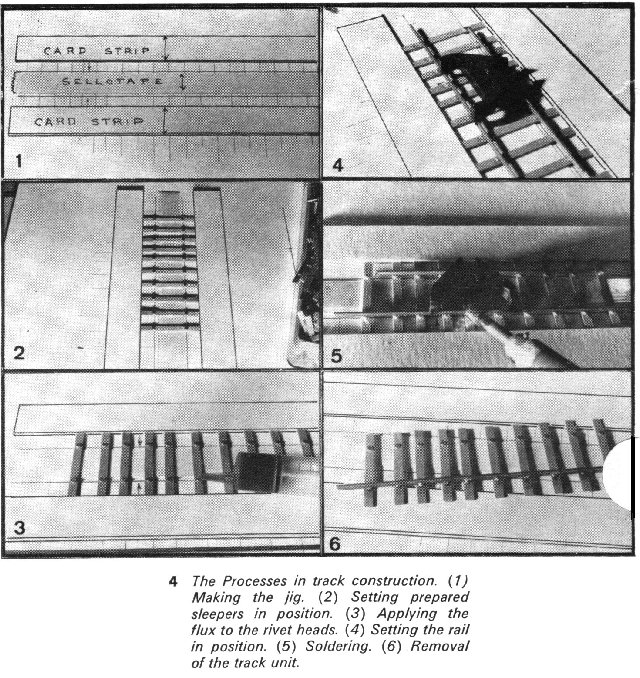
retention of the sleepers. The construction principles will be clear from the photographs.
If, following use, the centre-line strip of tape loses its tackiness, it may be replaced
(an advantage of the laminate top) or another strip laid over the first. This jig is
probably one of the quickest and simplest units which is capable of assembly, and for the
novice, it is well worth the hour or so spent in its construction in terms of experience
gained in making accurate track; for the experienced, a more permanent jig may well
appeal. The principles and aim of making track, accurately aligned in all axes, remain the
same.
We are now ready to make our first length of
correctly scaled permanent way in 4mm/ft scale.
Making plain track
The first operation that we must carry out is to
rivet the sleepers. This must conjure up a vision of a Chinese puzzle, where hundreds of
tiny components have to be set individually and riveted by hand, however, such is not the
case. The rivets are small, and we do not wish to handle them individually. A small pile
of rivets is scattered on a smooth and well-lit surface, and inevitably a number of them
will be positioned head down. The Protofour sleepers are ready-punched with two holes at
correct spacing, and it is only necessary to set the holes over the shaft of the rivet to
position the rivet in the sleeper. When sufficient sleepers are prepared in this way, they
are inserted in the runway of the riveting tool and the two rivets are set simultaneously.
The riveting tool is made from a standard
letterpress, which has had the letter dies removed and replaced with the riveting, or
alternatively the punching dies. The preparation of sleepers can be carried out at any odd
moments when the construction of track is not normally possible, and it is surprising how
quickly a stock of prepared sleepers can build up.
Compared with the time taken to describe the
process, the construction of the track is rapid. The prepared sleepers are set in the jig
against the sleeper lines, and checked, by glancing along the rivets from one end. that
they are properly level. If straight track is needed, both rails may be soldered in the
jig, but for curved track, only one rail is soldered. We therefore coat each rivet head on
one side of the jig with flux, using the syringe. The track gauge is set over the rail to
be soldered, and a short section of rail placed in the opposite jaw to assist in levelling
and positioning of the rail over the guide lines. The soldering may now take place, and it
is suggested that the rail be tacked at each end, and the remainder of the soldering
completed using the steel rule as a straight edge behind the rail. The important point to
consider is that the rail should be held down while soldering to ensure that it remains
flush with the rivet surface. When one rail is secured, the second may be soldered using
the rail gauge, or the unit removed from the jig and the next length commenced.
The object in soldering is to bond the rail on to
the rivet head with the maximum strength and minimum excess of solder. We are trying to
avoid a solder blob which might otherwise prevent the correct seating of the decorative
chair.
The completed track is remarkably economical in
materials and remarkably strong, and it is as accurate as the components that are used in
the jig. It is important to check beforehand that the rail is free from bends and kinks,
and this may be done by looking along the rail toward the light. Any defects should be
removed by running the rail through the fingers and pressing she rail to straighten out
the affected parts. Rail made from nickel silver may often be soldered without
preparation, but it is advisable to clean the undersurface (not the sides, which we do not
want to solder) with the glass fibre brush.
There is no worry about temperature expansion in the
jig, as the Sellotape grip is sufficiently mild to allow all the stresses to be relieved
regardless of the progress of the soldering. As noted already, it is important to ensure
that the rail sits flush with the rivet tops, and if any doubt exists on this score, the
soldering may be reworked until one is completely sure. We want the track to leave the jig
in optimum condition, and a little extra care at this stage will pay dividends in later
operations.
Preparation of the trackbase
Under this heading we refer only to the physical
aspect of preparing the base, and not to the delightful process of designing the layout,
which could well occupy a series of articles in itself.
In part four,
chipboard was recommended as the best medium for baseboards, and in order to save weight
and expense it should be used only where the tracks are to run. The bases should be
screwed to the framework, and checked for level and alignment.
A feature universal in the prototype and rarely seen
in the model world is superelevation. The inclusion of this feature gives a most authentic
touch to the track, but the change of rail levels involved requires extreme care in
execution. It might be possible where single track, or even double track perhaps,
continues unbroken in a curve, to pack the bases at the outside edge, but a better effect
is achieved by packing the underlay itself.
The cork underlay is cut to fit the bases, and
pinned in position with drawing pins. The trackage plan may now be marked out, and the
lengths of track from the jig placed in the positions they will eventually occupy. Drawing
pins hold the lengths in position, and when they are satisfactorily secured, the remaining
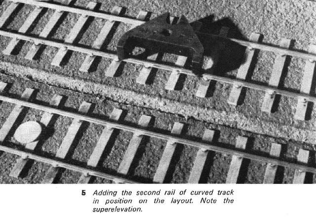
rail of the curved sections is soldered in position. This is carried out with the
assistance of the track gauge, and the three-point suspension, with the single claw on the
inside of the curve, automatically adjusts the gauge widening. Again, it is important to
press down on the rail while soldering, to ensure firm contact between rail and rivet.
When the track is completely assembled, the cork
underlay may be bonded to the bases. Where superelevation is called for, a thin strip is
first glued in position on the underside of the underlay, its location noted from a cut
made along the outer line of the ballast on the upper surface. This strip must be tapered
very gradually at the transition from curved to straight track, to avoid sudden changes in
rail level which might tend to allow derailments. When bonding to the bases, liberal
adhesive should be placed to give the best grip to the underlay where it leaves the base
and rises to the super-elevation strip. The inner level of the underlay should be well
secured by drawing pins during bonding.
When the adhesive is fully set, the underlay should
be tapered as necessary to give the correct shape to the ballast, and brushed clean in
preparation for tracklaying. And for tracklaying, we must wait until the next article in
this series.
Letterpress rivet and punch dies
The diagram shows a typical arrangement of
letterpress jigs for punching and riveting, Protofour crossing timbers and sleepers. The
tools themselves are formed from 1/8"in dia. steel axles, force fitted into reamed
holes. The punch tip is the shank of a 3/64in or 1.2mm drill, ground flat at the business
end. The straps are needed to allow the punch to pull clear of the timber, on completion
of the operation.
In the riveter the timber, with rivets inserted
moves down the runway, which is the correct depth to accept the head. The runway bolts
prevent the crushing of the timber by limiting the travel of the punch.
Note. The adhesive mentioned is
"Manhesive", and a large can is obtainable at builders merchants for 17s. 6d. It
may be thinned with a little water, and brushes washed under a tap immediately
after use.
[Part 6 will appear next
month]
Copyright - Model Railway Study Group, reproduced with permission.
Back to Magazine Index, Back to Site Index.