| Model Railway Constructor - Issue number
400 |
August 1967 |
PROTOFOUR --- 8
a new scale modelling standard
by a model standards study group
J. Brook Smith, M. S. Cross, D. E. Jones
W. L. Kidston, B. Morgan, Dr. B. Weller
|
|
Constructing Turnouts
Equipment needed
Pentel pen* (nylon tipped pen).
Pencil or fine drawing pen.
Steel rule with mm markings.
Thin card or Bristol board.
Double-stick sellotape.*
Protofour data sheets or turnout diagram.*
Soldering iron (Solon 25watt).
"Savbit" solder and flux.
Glass fibre brush.
Facial tisues for cleaning.
Fine flat file (and medium file if desired)*
Skarsten scraper.*
End cutters and square-nosed pliers. *
Kingsway "Dead Scale" Bullhead rail.
Protofour rivets.
Protofour crossing timbers.*
Riveting and punching* tools (letterpress).
Track gauge and crossing flangeway gauge. *
Check rail gauge.*Items marked (*) are
additional to normal trackmaking equipment. |
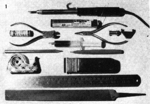
1 Protofour Equipment. Note the glass
fibre brush, check and track
gauges, flux in syringe, scraper and double-stick tape. |
General
Protofour techniques emphasise that good model railway running is directly dependent upon
the accuracy with which certain critical dimensions are incorporated into the wheels and
track.
Next to the contour of the wheels and rail, the most critical components are the crossings
and switches, and our main concern in this article is to use a constructional technique
that will ensure the accuracy of these components. This inevitably leads to construction
in a jig, which need not be complicated as previous articles have shown. It may be only a
sheet of card, or Formica laminate, on which the running edges of the rails, the main
settings of the turnout, and the leading edges of the timbers, may be drawn. By
photostatting the drawing of a turnout in the previous article, and sticking this to the
jig surface, marking out may be avoided altogether. A third alternative is to use
Protofour templates which are already available for several types of turnout. However, for
non-standard turnouts or for junction layouts, marking out will be necessary.
Marking out
For convenience, the Study Group has made out data sheets giving the leading dimensions of
every combination of switch and crossing in millimetres in 4mm scale, and these dimensions
may be translated directly to the jig.
Assuming one road of the turnout to be straight, a single line is drawn across the jig,
which will represent the line of the running rail through the crossing. Another line is
drawn parallel at 19mm spacing, so that when looking down on the jig, the lines will just
be visible when the rails are correctly set in place. The first mark is made at the toe of
the switch, and from this the "lead" is marked off to give the position of the
nose of the crossing. This latter point is now the datum for every other dimension of the
turnout.
The crossing angle is given as a ratio, e.g. 1:10, and by marking ten units along the
running rail from the nose of the crossing, and one unit at right angles, the line drawn
between this point and the nose will give the correct crossing angle of the curved road;
half a unit will give the centreline of the vee. This measurement should be in reference
to the centre line of the vee; for model purposes, units at right angles to the running
rail give an equivalent and more convenient positioning.
The next points to establish are the heels of the switches, which are standard for each
type of switch. Between these and the crossing nose the closure rails describe the radius
appropriate to the lead of the turnout. This may be marked in with the assistance of a
flexible metal rod in preference to the trammel which might otherwise be required. The
curved road's 19mm distance marks are drawn in and the rod used again to mark the position
of the stock rail. It will be noticed that there is either a "set" or a
"joggle" in the stock rail 4in ahead of the toe, and an equivalent
"set" in the angle of the switch rail for the curved road. The set must be taken
into account when marking out the switch positions.
Switch timbering follows a standard, if irregular pattern, with spacings approximately
2ft 4in interval. Crossing timbers are spaced evenly at 2ft 6in interval, but they may be
aligned at right angles to the main road, or at right angles to the crossing centreline.
When the appropriate system has been chosen, the timber positions are marked in as a
single line representing the "leading edge" of the timber, commencing, as
always, at the datum point at the crossing nose. Note especially that a timber always lies
under the nose of the vee (for the "A" chair) and under the toe of the switch
rail. Timbering under the closure rails often depends upon the situation of the turnout,
but spacing is usually about 2ft 3in.
To complete marking out, the flange contact face of the check rails is marked, and also
the limits of the wing rails. Check rails usually chair over five timbers, but the LNWR
used only four chairs on occasion.
Preparation of Components
1. Timbers.
The jig is now complete, and it requires only two bands of double-stick tape to retain the
sleepers, laid outboard of the running rail lines, to prepare it for assembly. A third
band of tape may be laid below the crossing if desired, for greater stability.
Protofour timbers are specially cut to even width, and are 1ft 0in long, for smooth
passage through the punch and rivet tools and for ease of handling.
The timbers are set across the jig against the timber marks, where they are held
lightly by the Sellotape. Some excess length may be left on the shorter timbers for
convenience. The timbers are identified by marking, commencing with the "A"
timber below the crossing nose, B - D away from the toe and X - Y towards. The remainder
are numbered consecutively from the toe, and the numbers repeated on the jig. It does not
matter how much we disfigure the timbers with marking, as this surface will become the
undersurface, and will be hidden.
The position of the rivets is next marked by a Pentel dot immediately
outboard of the running lines, except where slide chairs occur at the switch rails. Only
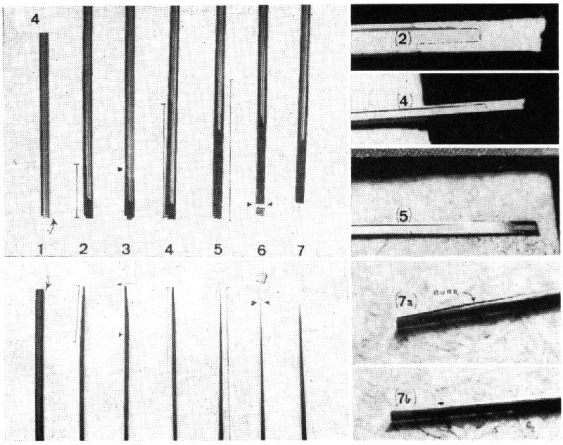
the stock rails are marked here. (Photo No. 2). At the crossing nose, a
standard pattern is adopted, two adjoining rivets on the "A" timber and three
adjoining rivets on the "B" timber, symmetrical with the centreline.
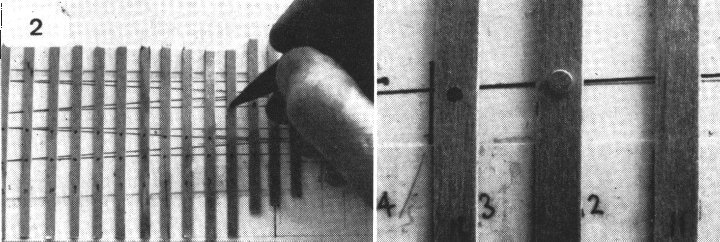
2 Marking the timbers with the Pentel pen.
Enlarged section shows (R.) a plain timber already numbered; (L) marked ready for
riveting, and (ctr.) the rivet set and the timber returned to the jig.
When all the rivet dots have been marked, including those for the check
rails, the timbers are removed from the jig, which latter is put carefully away from dust
and debris until required for assembly. The timbers are next slid through the punch tool,
and every dot is punched through as it arrives below the tool face. (Photo
No. 3). The rivets are scattered on a smooth flat surface, and the timbers, marked
side upwards, are hooked over the rivets which are sitting shank upwards, until all holes
are filled. The prepared timbers are next fed through the press tool and each rivet set in
turn. This operation is both simple and speedy, and without further preparation the
timbers are ready for resetting in the jig. Now we must prepare the rails.

3 Letterpresses containing the riveting and
punching tools. At right a timber being slid through the punch and the marks punched
through.
2. Rails.
Rail filing must be carried out methodically for the correct results to be obtained. For a
filing surface, a piece of hardboard overhanging the edge of the bench or table will be
found ideal, alternatively, a piece of blockboard set on edge, and screwed to the bench or
a bench block, may be used. The filing of both point and splice rails, and switch rails,
follows a similar procedure, with the exception that the planing of the former is flat and
the latter slightly concave. This concave surface allows the toe of the switch to lie
flush with the stock rail whenever the switch rail is held against it. A newspaper should
be spread to catch the filings, which are otherwise difficult to clean away The operations
are as follows: (Photo. No. 4)
| 1. Select plain rail of sufficient length, and identify the thicker running rail head. 2.
File a �in (point rail) or �in (switch rail) bevel until the filing runs well into the
web. (This will become the running edge of the rail, so position the head for LH or RH as
necessary.)
3. With the square-nosed pliers, bend the bevel flush with the running rail edge once
more.
4. Filing flat and carefully, even off the bevel until it is a smooth continuation of
the running rail, which may be seen when metal is being removed from the remainder of the
rail. |

4 The several stages of switch and point rail construction,
with numbers referring to the description in the text.
|
5. Turn the rail over, and file the appropriate point or switch rail
bevel. For the latter, the coarser file may be used, but finishing should always be with
the fine file. The point rail should be firmly supported during this operation, but the
switch rail is best filed on a flexible surface, such as a Formica sheet projecting over
the edge of the bench. The pressure of the file flexes the sheet and rail, resulting in a
deeper cut at the centre of the bevel than at the ends. When the pressure is released, the
bevel becomes slightly concave. (see diag.).
6. The paper thin metal at the tip of the rail is next removed with the end cutters,
leaving a firm, neat, thin "point." Check in both stage 4 and stage 5 that the
bevel length and angle is appropriate to the pattern of the turnout.
7. The filing will produce burrs along the edge of the rail, especially if the file is
not sharp. (Always use a new file for these precise operations.) The burrs may be removed
with the scraper, which should be kept well sharpened on the oil-stone. It may also be
found advantageous to use the scraper to clean up the bevels. Although the procedure
sounds complicated, the filing of switch rails should not take longer than 3-4 minutes,
but it is method and accuracy that count, not the time taken. Extra time is often well
spent, as mistakes in manufacture cannot be rectified once the rail is laid.
Alternatively, ready-milled switches may be obtained from Wing Commander Burns, ("The
Tender", Satchell Lane, Hamble, Hants - usual disclaimer - no connection with the
Study Group) who specialises in producing top quality trackwork.
Assembly
1. Components.
To produce one turnout, we require the following: Two switch rails, to comprise switch,
closure and wing rails in one unit, planed in opposite hands, i.e. LH and RH. Two stock
rails, each the overall length of the turnout. Two point rails of opposite hand, to form
the point and splice rails respectively. Two check rails (offcuts of the above during
assembly, to save cost). Timbering, riveted according to the turnout requirements.
2. The Vee.
The assembly of the point and splice rails into a vee is best carried out in a separate
jig, on which the crossing angle is redrawn. Using the double stick tape, two pieces of
hardboard or card, with undamaged vertical edges the depth of the rail, are mounted to
form a hollow wedge at the nose of the crossing. First the rails are cleaned with the
glass fibre brush and the tisues, and then the point rail is inserted to the end of the
wedge. The splice rail is then brought to a snug fit behind it, the two coated with flux,
and soldered with a hot iron to form a solid unit. On removal the vee is cleaned with a
tissue, and then a file is run lightly over the edges to remove any solder standing proud,
which might otherwise interfere with the running.
3. The Timbers.
These are next reset in the jig, according to the numbering, making sure that they are
pressed firmly into the tapes, and are accurately positioned.
4. Setting the Vee.
As the nose of the crossing is the major reference point, we commence by setting the vee
as accurately as possible. Flux all rivets for the vee, point and splice rails. Reclean
the rails with the brush and tissues, set in position, and check that the nose is over the
reference point and the running rails are aligned with the lines on the jig; temporarily
tack-solder one rail at the "D" timber. Recheck the nose alignment and solder
the tip of the point rail in position. Recheck and adjust if necessary. Finally, tack the
remaining rail at the "D" timber, and work towards the nose, soldering every
rivet. The advantage of the Protofour system is that the position of the components may be
checked at every stage of construction, and adjustments carried out without damaging the
track in any way.
5. Setting the Stock Rails.
Having positioned the vee, we next locate the switch toe. A slight but accurate set or
joggle is put in the stock rails as required, and the set located 1-2mm ahead of the toe.
Using the guide lines, the straight rail is "tacked" at the toe, and, using the
track gauge, opposite the crossing. The curved stock rail is similarly located using the
track gauge for both toe and crossing. Of course, the rails will have been cleaned and the
rivets fluxed before soldering. Do not do more than tack the rails at this stage.
6. Setting the Switch Rails.
Now that there is a reference point at straight road switch in position. Locating both toe
and crossing, we may set the the toe accurately, a mark is made on the closure rail at the
crossing nose. Transferring the rail to the turnout diagram, the divergence of the wing
rails ahead of the crossing is marked, and the square-nosed pliers used to set the correct
angle of the wing rails. The rail is then cut to length with the end cutters, and then
gripped along the web and filed flat to show the end section of the rail correctly. The
curved switch rail is similarly marked and trimmed. The ends of the wing rails are splayed
according to the turnout diagram.
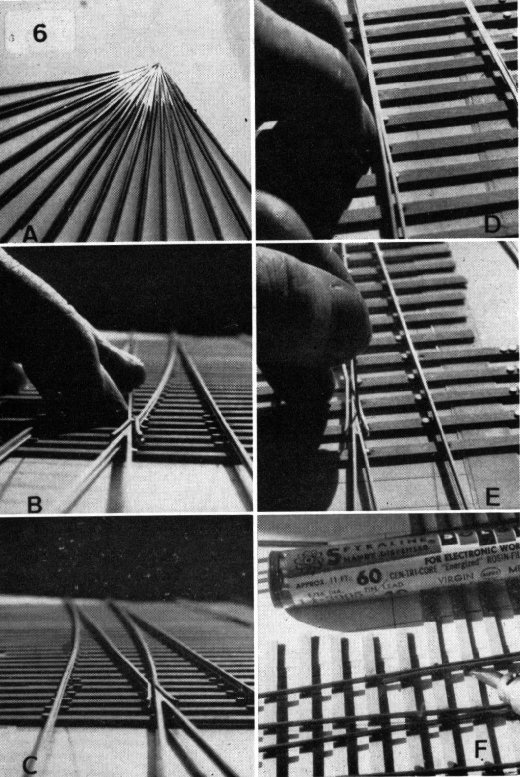
Check that both switch rails are capable of fitting snugly into the stock rails (Photo. No. 6) and that lengths and angles are correct. Now for
accurate positioning.
In setting the switch rails we are also setting the crossing flangeway, which has to be
absolutely correct in both spacing and alignment. Flux all closure rail and crossing
rivets, and clean the switch rails. Position the straight switch rail with the original
mark opposite the crossing nose. Using the flangeway gauge (or a No. 71 drill) to space
the crossing flangeway at 0.65 - 0.68mm, we look along the point rail (which is always in
the main road of the turnout) to check that the switch rail/wing rail is in alignment with
it. If it is not, the switch rail must be moved forward or aft to attain this alignment,
and then be tack soldered at the "X" timber. The alignment can now be rechecked,
and when it is as accurate as possible, the steel rule is set against the nose and the
toe, and the closure rail held against it while soldering from wing rail to heel. Finally
the drill is held in the flangeway and the wing rail held against it while soldering in
position. The same procedure is used for the curved switch rail except that the guide line
is used instead of the steel rule to set the closure rail. Check that there is no change
of angle where the curved closure rail meets the crossing nose a sudden change of radius
at this point will result in unsteady running.

|
6 a. Completed Vee's. showing the evenness resulting
from jig construction.
b. Adjusting the switch at the crossing.
c. The completed crossing. Note the continuation of the running rail alignment
through the crossing.
d. Checking the fit of the switch rail against the stock rail preparatory to
soldering the latter.
e. Checking the crossing flangeway with a No. 71 drill before soldering the wing
rail.
f. Soldering the check rail in position. |
7. Finishing off.
The stock rails at the toe of the switch may now be soldered, checking that they fit
naturally to the planing of the switch rails. Once this has been completed, the track
gauge is used to position the stock rails, soldering progressively towards the crossing.
The gauge will automatically provide gauge widening on the curved road, but at the
crossing the gauge should be as close to the nominal value as possible.
Always make sure that the rails are held down on to the rivets while soldering, or rail
inequalities may be found. These can always be removed by reheating the joint, but they
are better avoided altogether.
The check rails may be cut to length from scrap rail, filed square, and given their
characteristic flared ends. Note that this flare is very slight, about the thickness of
the rail at the maximum. The check rails are set using the check gauge, and this relates
the positioning to the crossing, and not to the adjacent running rail. The check rail
flangeway is thus the result of the difference between check gauge and track gauge.
This completes the construction of the turnout in the jig. It may now be prised away
from the tapes and the jig put away for future occasions. The completion of the turnout,
by the fitting of electrical connections, slide chairs, tie bars, etc., is better carried
out when the track is laid. This last procedure has already been described for plain
track, and no further comment is necessary. It will be seen that the use of Protofour
techniques has resulted in a strong, neat, and accurate turnout. It will also be realised
that the same constructional techniques can be applied equally successfully to all other
scale and gauge combinations in model railways. It is hoped that the emphasis on the
crossing nose as the origin of turnout dimensions will help to counter some constructional
techniques advocated in the past, which, while ingenious, are basically unsound. These
include the half jointing of point and splice rails to provide continuous rail from the
switch toe to the end of the turnout, and methods involving the movement of the vee to a
position midway between arbitrarily mounted stock rails. It is also true to state that at
the time of writing, Protofour is still the only way in which a correctly proportioned and
accurate turnout may be obtained, short of custom units ordered from specialist firms. If
only for showcase purposes, the method is worth trying; on the other hand, it could be the
beginning of a new and rewarding dimension in scale railway modelling.
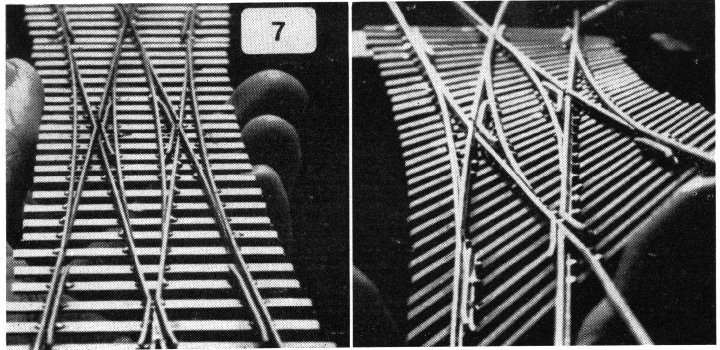
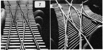 |
7 The completed turnout - in this case a double slip -
immediately after removal from the jig. The strength and flexibility of Protofour
construction is demonstrated by twisting the unit 45 deg. out of line. All the main
alignments remain unaffected and the solder joints undisturbed. |
PART 9 NEXT
Copyright - Model Railway Study Group, reproduced with
permission.
Back to Magazine Index, Back to Site Index.
K Norgrove 25/04/03