Diesel/Electric Drive ideas.
This page has resulted from discussions initiated by Richard Tearle and contributions
from Russ Elliot and Andy Reichert.
So far it contains some illustrations of the various bits and pieces discussed.
1. Overland Models/Ajin Precision drive system
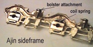
This system is fully sprung with a coil spring to each axlebox and uses a 15:1
reduction gearbox for each bogie linked to 1:1 spiral gears for each axle. The drive is
fully reversible, ie pushing the loco along the track will spin the motor.
Construction is simple, operation smooth, if it has a weakness it is the bearings which
do not look durable, just holes in 0.5mm plate.
The gearboxes are, however, superb - smooth quiet and solidly engineered.
Click on the pictures for larger versions.
|
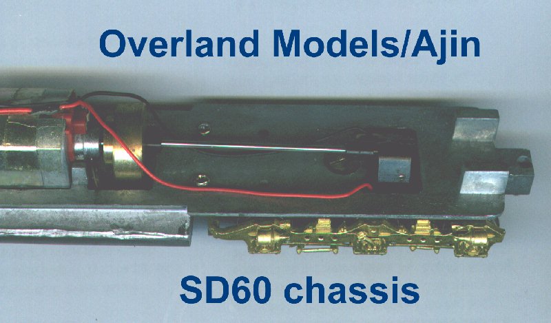
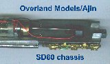
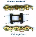
This shows the top view of the Ajin chassis showing the drive shaft and universals to
the reduction gearbox which is integrated with the final drive to the centre axle and
supported on the axle. |

|
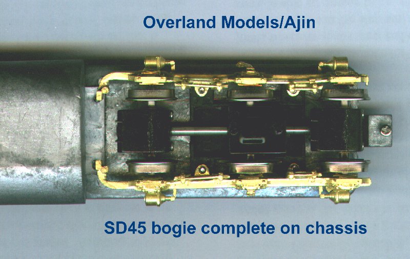
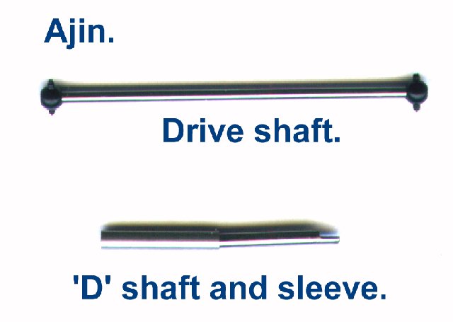
Here we see the bottom up view, the three gearboxes are linked by 'D' shaft and sleeve
couplings which allow freedom for the individual wheelsets to move on their springs but
are rigid enough to act as the torque arms for the gearboxes.
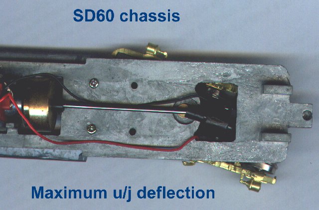
(Where I wrote SD45 please read SD60, not that there's much difference but the chassis was
actually intended for an SD60) |
|
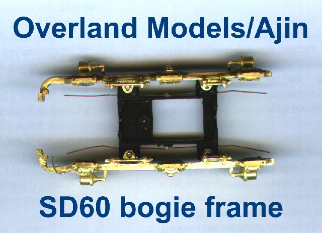
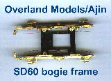
This is the frame sans wheelsets, very straightforward. |
|
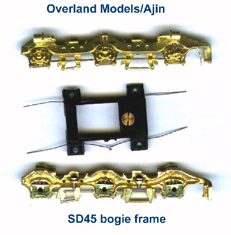
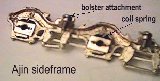
And the component parts, electrical pickup by the wipers attached to the plastic
stretcher. |
|
Here details of the springs and bearings, the axle end actually bears on the hole in
the retaining plates, the hole in the axlebox proper is larger. The plates could be
replaced when worn but I suspect the retaining lugs which are part of the lost wax axlebox
will break and a new fixing would have to be devised. |
|
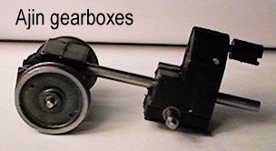
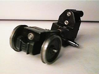
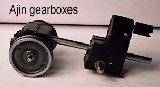
These pics show the two types of gearbox with a P4 wheelset, the wheels
are on the original axle and the axle end is not long enough for outside bearings so
longer axles need to be substituted. |
|
|
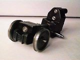
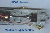
This pic shows the limit of the drive shaft u/j. At this angle they operate
comfortably. |
|
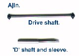
Here one of the motor - reduction gear drive shafts and a 'D' shaft from the end
gearbox with its sleeve. |
2. Some of the Exactoscale components
|
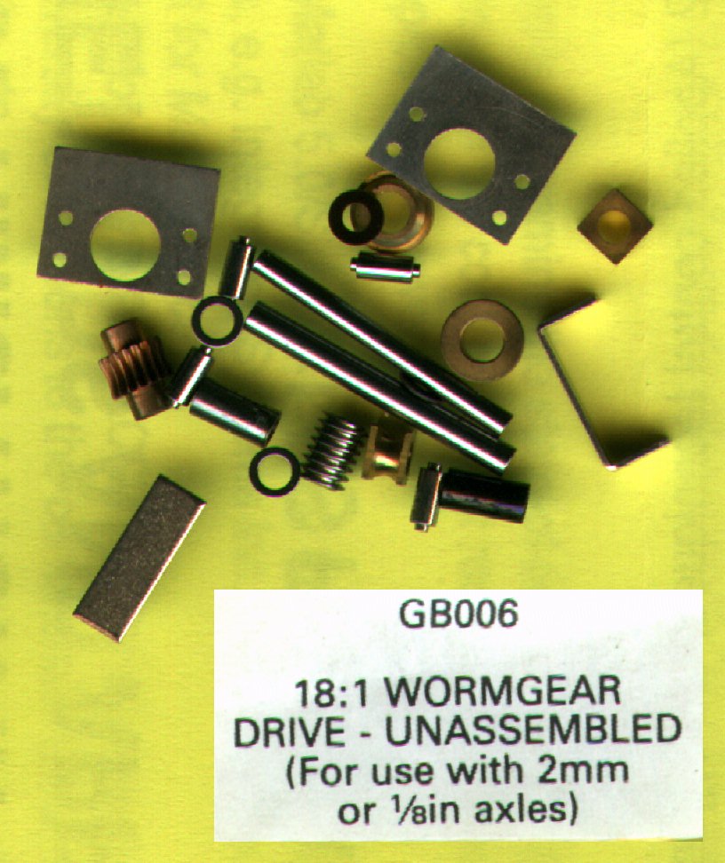
This is the kit of parts from exactoscale, assembly needs care, check here how
Ted Scannel does it. |
|
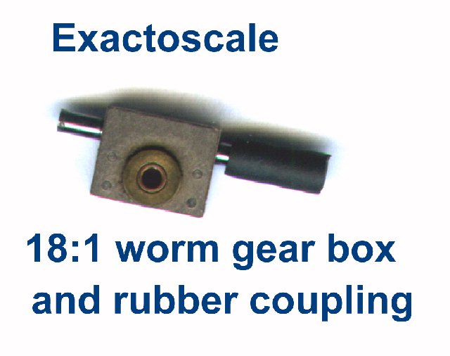
The assembled result. |
|
And connected to an Exactoscale rubber coupling, these are no good as a u/j but do
give a bit of resilience in a drive line, and may be OK for similar use to the Ajin 'D'
shafts above, although I haven't tried it! |
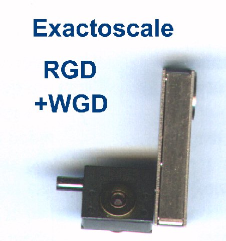
|
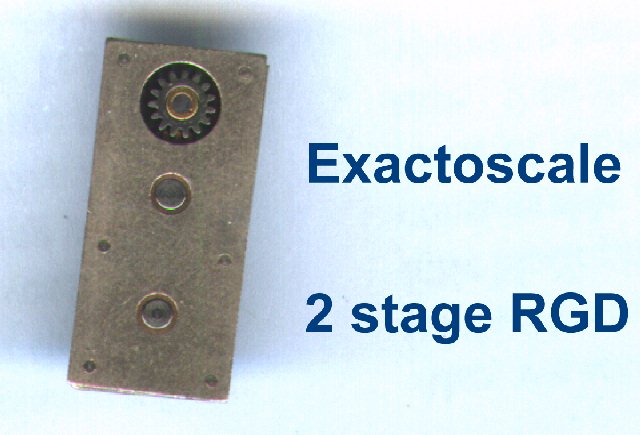
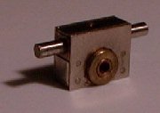
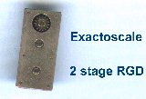
This is the 2:1 reduction box, the centre axle has an idler gear same size as the
bottom gear, the single stage unit has just the one large gear, the 1:1 box has two of the
larger gears. |
|
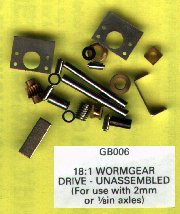
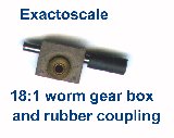
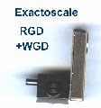
Here the RGD is linked to the 18:1 worm drive. |
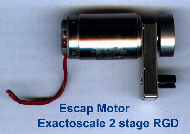
|
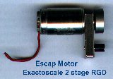
This shows an Escap motor and small flywheel attached to an RGD, this was in
preparation for a tender drive but is equally applicable to Richard's Scheme 2. |
For further information on this topic try Richard Tearle's proposals
and/or Andy Reichert's Electro-Glide
system.
Return to homepage
Copyright Keith Norgrove.
Last revised: August 27, 2003