The Crossing Vee
|
I
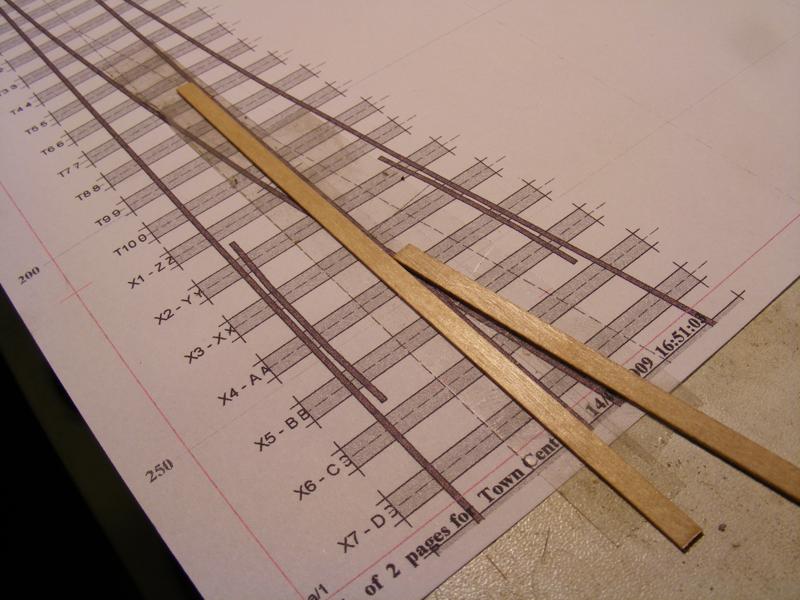
followed my normal practice of using two
offcuts of timbering to make a jig for the vees prior to fixing the
timbers in place to continue the construction. The jig is used
initially to check progress of the filing until the angle of the rail
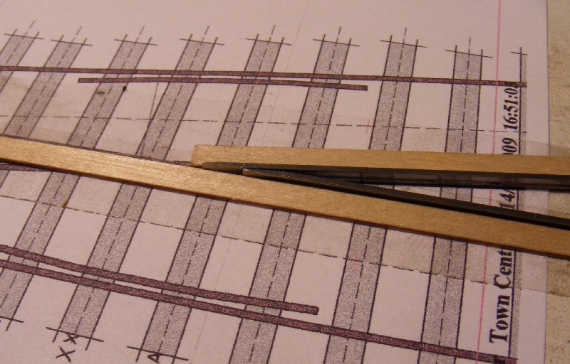
end is a snug fit in the jig. The point and splice
rails are then soldered together upside down in this jig.
|
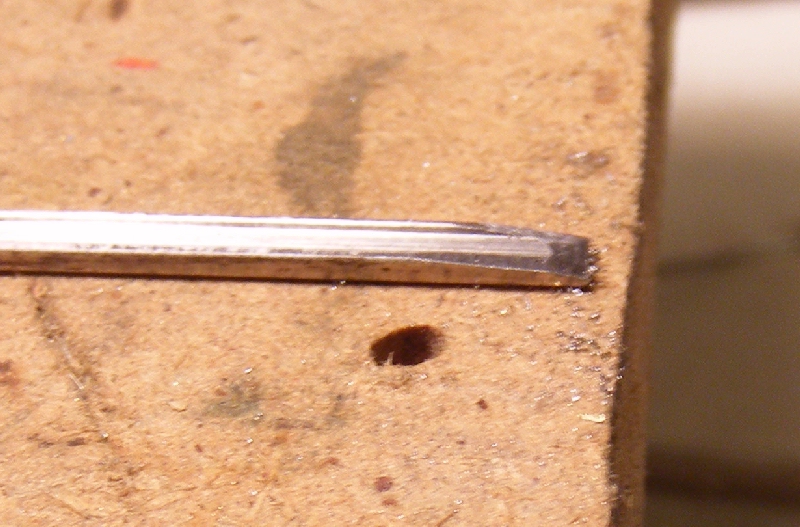
Filing the Vee
|
File
one side of the rail first until nicely into the web, then use a pair
of pliers to bend the rail so that the filed face is in a straight line
with the rest of the rail on that side.
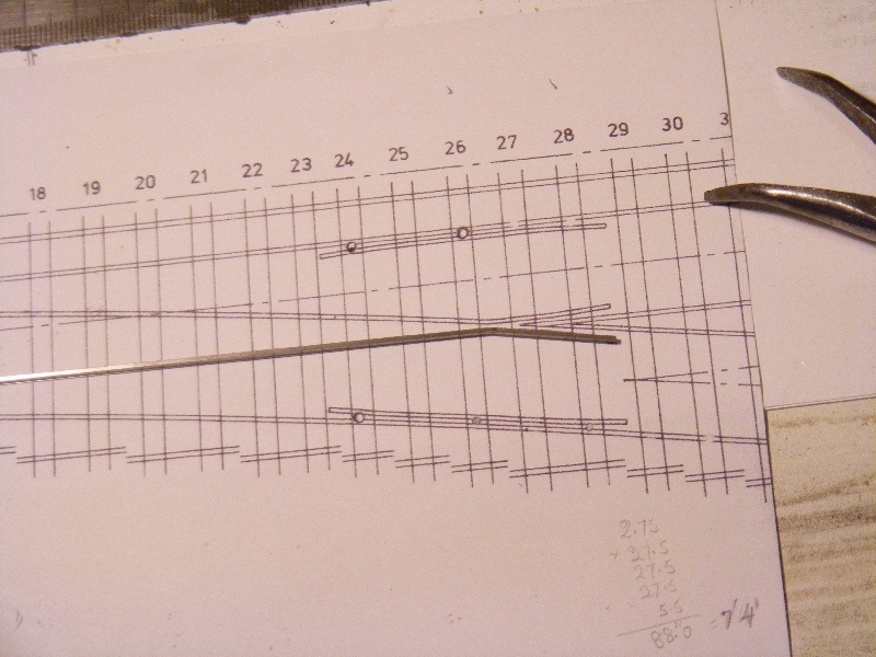
Then complete the filing from the other side, marks on the filing board
6 times the rail width apart (for 1:6 crossings) will help gauge the
angle and it can be checked in the vee jig.
|
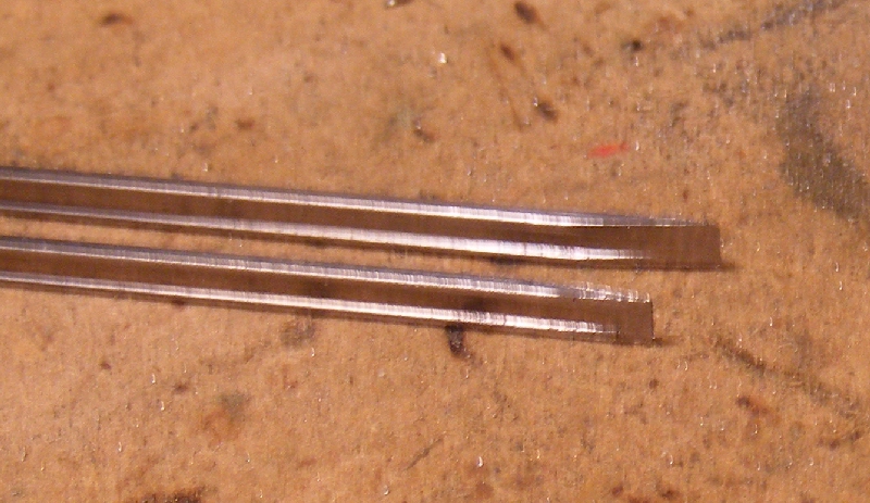
Make two such rails of opposite hands, so one can be used for the point rail, the other for the splice rail.
Assembling the Vee
The rails are first tried in place in the jig and when satisfied
with the fit removed and replaced with a dab of solder paste in the
joint.
|
When
finished you want the point rail to be in the normal, or main road, the
splice rail in the diverging road. It appears to be the other way round
in the photos because I always solder my vees with the head down and
held by the double sided tape. This ensures that the running surfaces
are held properly by the jig and keeps any tape residue off the bottom
surface which needs to be clean for soldering to the rivets. A touch
with the iron will melt the solder paste and give a good joint.
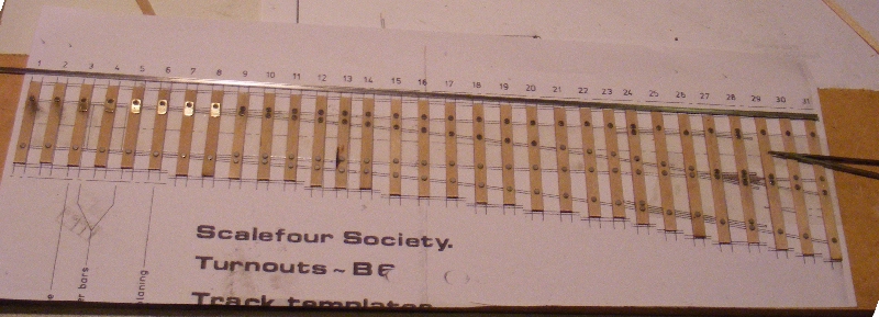
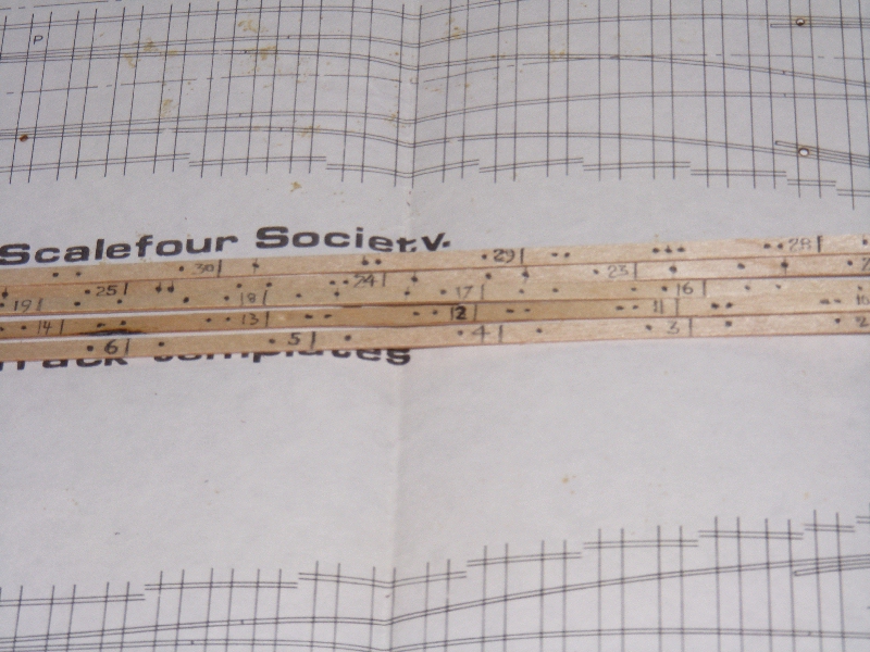
Preparing timbers
Note
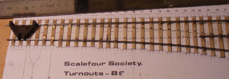
I am using a different template here, I decided to use an old Scalefour
society template to show that its not essential to have "Templot"
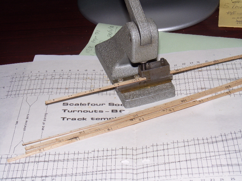
I always mark out all the timbers on the 12" strips and complete
all the punch and rivet work before cuttng the strips to length. This
minimises waste, if you start marking out from the crossing end and
work towards the toe, then when the next timber no longer fits you
should be able to fit one of the shorter ones at the end of that strip.
Mark the ends of each timber, its number and a dot where each rivet
needs to be. The original P4 templates have dots to show you where,
"Templot" provides a timber centreline, with these old Scalefour
templates you need to estimate or mark where the rails intersect the
centreline of the timber.
The strips are now run through the punch making a neat hole for each rivet position.
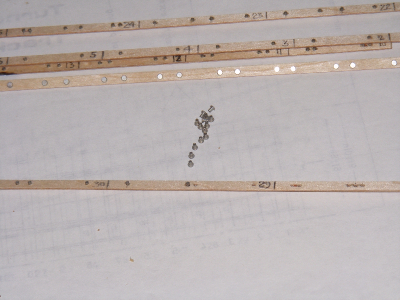
Then
loaded with rivets, keep the rivet heads on the unmarked side to make
sure all the markings end up underneath the turnout. Use the end of the
strips to tease out a line of rivets and persuade them to stand up
nicely, then work along the line of rivets putting a hole over each
one, with a good light and a bit of practice you soon get the hang of
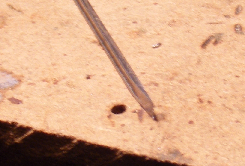
it. If you find this difficult a scriber can be used to help the
alignment by putting the point down through the hole and the tip into
the end of the rivet.
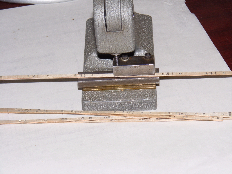
Once loaded the final job is to run the strips through the press tool.
|
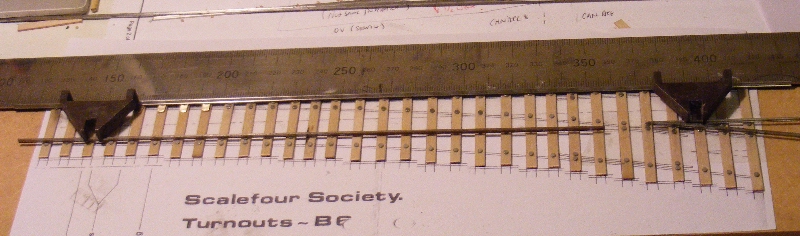
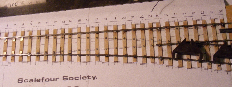
Assembling the Turnout
|
The timbers are cut to length and stuck to the template with
double sided tape, here the vee and straight stockrail are ready for
fitting and a set of Bill Bedford slide plates have been prepared for
the straight stockrail. The Bill Bedford plates are available from Scalefour stores as item 165, or from Eileen's emporium.
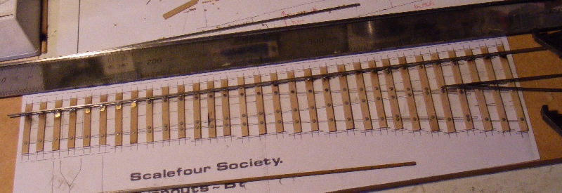
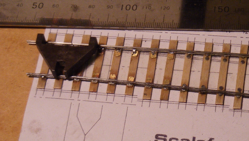
Here
the rails are held in place with a pair of track gauges to confirm fit.
A steel rule is used to keep the straight stockrail straight. A spare
piece of rail is used to keep the left hand gauge level.
Don't worry if you only have one track gauge, you can manage perfectly
well with one and most of my track was built that way, but a
second set does help and a chance find at the Scaleforum bring and buy
provided mine.
When ready the rails are temporarily removed, the rivets and rail foot
cleaned up with a fibreglass brush, a dab of solder paste put on each
rivet, the rails put back in place and the stock rail soldered.
The vee is then carefully positioned, with one (or two) gauges and also soldered in place.
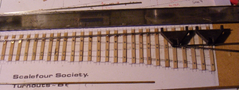
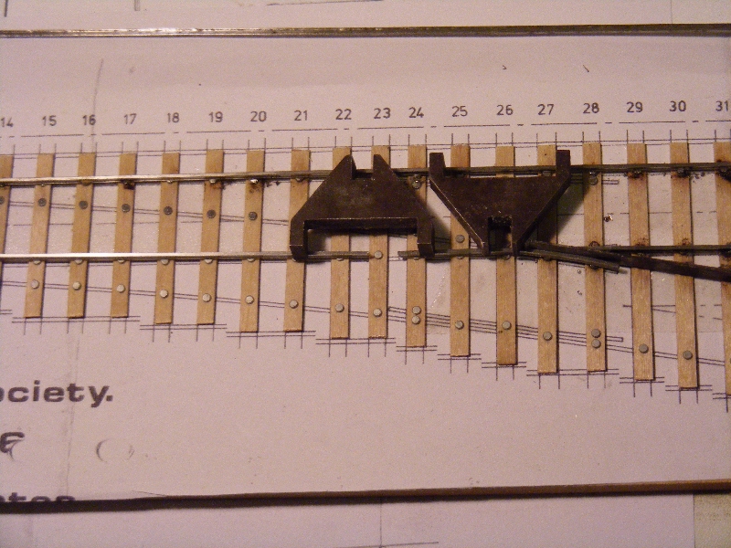
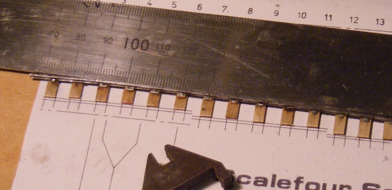
The next task is to prepare the straight wing rail, an unused template is used to check that the bends are to the correct angle.
Once happy with the bends the rail is cut to length.
The
wing rail is held in place by track gauges and a crossing flangeway
gauge and soldered. Use the steel rule, or a block gauge if you have
one to confirm that the alignment from wing to nose is straight, take
it off and repeat if any error found as alignment here is important for
good running.
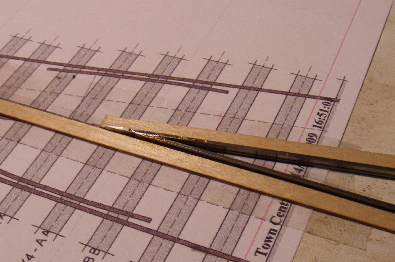
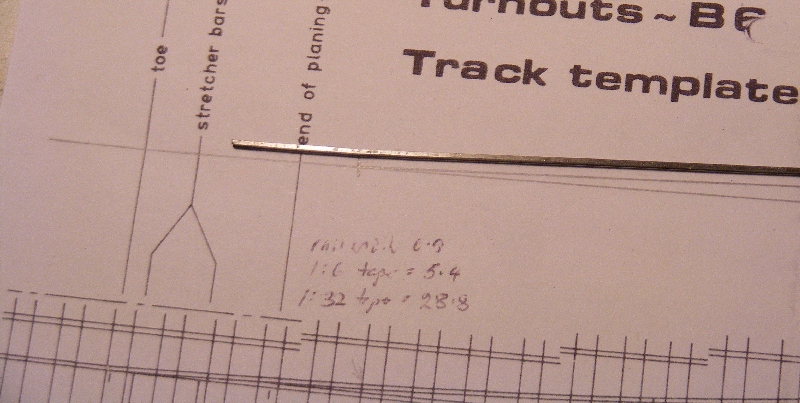
Next
job is to prepare and fit the curved stock rail, this rail has a set
just before the blade toe so that the initial angle of divergence is
the same as the planing angle of the blades, important for a good fit
of the blades without any gauge narrowing. Its difficult to judge this
accurately from the template due to the curve in the rail so I find it
better to draw the angle as shown here. In this case the planing angle
is 1:32. The rail complete with set is shown next to the drawn angle,
it doesn't look much but its important to get it right. (Note I have
also calculated the planing lengths for both the vee rails (6*0.9 =
5.4) and the blade (32*0.9 = 28.8)).
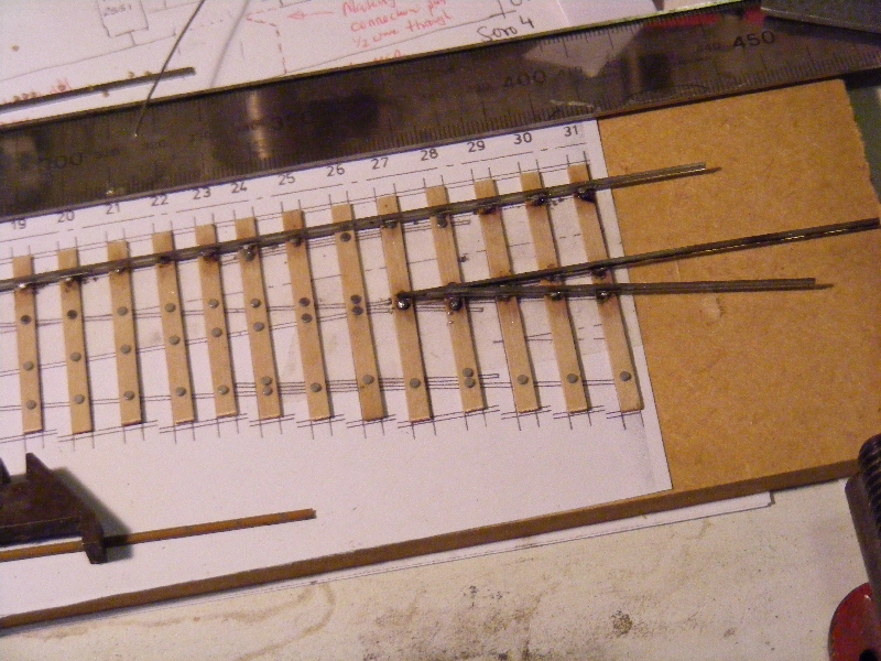
The
stock rail is held by one gauge on the straight portion at the toe and
the rail curved between finger and thumb to fit the template, note that
the planing length (as calculated above) should remain straight to fit
the blade. Once happy with the curve solder in place, don't forget the
slide chair plates. Start at the toe where the rail is held by the
gauge, and the straight section over the planing length, then transfer
the gauge to hold the stock rail to gauge from the previously soldered
vee and complete the soldering.
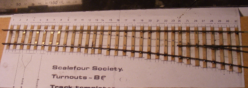
Holding the steel rule against the straight planing length shows up the set clearly.
Its now beginning to look like a turnout.
|