 |
|
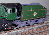
I had a need for a BR1d tender to go behind my old Brittania, a Bachmann tender was aquired some time ago and needed a P4 chassis. When Comet brought out their BR1 chassis and underframe kit last year I decided to give it a try. The running gear of this tender uses functional inside frames leaving the outside frames as dummies. The kit is designed for drop in wheelsets and is intended to be built rigid or as a standard flexichas. I did not care for either of these alternatives and decided to try a springy beam arrangement ala Ted Scannell. I am very pleased with the running qualities of the result and recommend the technique.
So what follows is my effort. (Underlined text links into relevant pictures).
These went together almost exactly as specified in the Comet instructions. I changed the buffers for sprung ones, and added the water pipes to from the filters to run behind the front steps. By drilling the filter body to fit on the pipe end then soldering the body to the frame the filters are held more positively than relying on glue alone, useful as they are placed where fingers catch them when picking the model up.
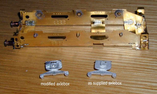
The main omission from the instructions concerns fitting of the axlebox/spring castings. They cannot just be glued in place as instructed as there is a substantial boss on the inside of the casting which must first be removed. I made the fitting easier and more secure by using a set of 2mm pinpoint bearings. The bearings were soldered in the frame holes as if they were to be used, then after removing the boss from the casting (Xuron rail cutters do this quickly with minimal cleaning up) I drilled a 2mm hole in the box so it fitted over the bearing so giving accurate location for gluing and additional strength.
The original and modified axlebox/spring castings with the soldered up frames.
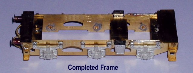
This is where the real work is, Comet provide two sets of spacers, 00 and EM so I made up the basic frame for EM, filing off the pips from the axle slots to allow upward movement of the axles as instructed for an equalised or sprung version. Then I spent quite some time contemplating it and my box of bits to see how I could fit the springy beams. For a six wheel chassis four beams are needed and to get equal loading on the axles the pivots should be 1/3rd of the axle spacing in from the outer axle. The end axles thus carry 2/3 of the load on their beams and the centre axle 1/3 of the load on each set of beams, making 2/3 again. With rigid spring beams acting as cantilevers, although this would give correct weight distribution when static, the double free length of the springs acting on the centre axle would result in softer springing for that axle. I felt that this may be a problem so chose to move the pivots inwards slightly. Equalising the spring rates would suggest moving from a ratio of 1:2 to a ratio of 1:1.414, I compromised at 1:1.5 which seems to have worked out OK but I don't really think its critical.
The inner frame is cut away between axles so cannot be drilled for a pivot axle in the correct place, I therefore had to solder on plates for the pivots which did allow the height to be confirmed before final soldering.
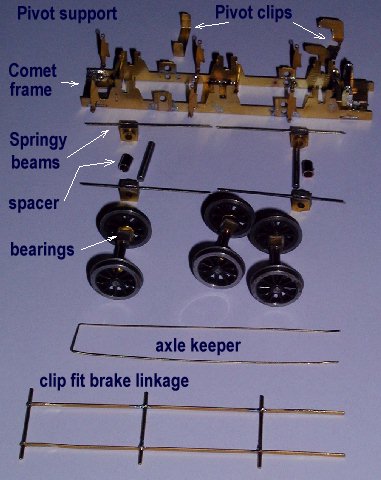
I had now to arrange how to mount the beams and how to take the load on the axles. I decided to solder the pivot beams to a bearing so that they would be free to rotate on their axles and would not need any complex retainers at the ends. For this I used the grooved square bearings from an MJT 2mm hornblock set, the beams, made of steel wire were soldered into one of the slots and normal 2mm axle stock used for the pivot axles. To take the load on the axles Exactoscale 2mm square bearings are used, they take the vertical loads only, the axles are retained fore and aft by the Comet frame slots. This is fine for a tender as there are no traction forces to contend with. The pivot axles are cut to length and held in place by U shaped clips fitting over the top of the frame and held in place by the tender body. The whole thing can be dissassembled by removing the two screws provided by Comet, unclipping the brake linkage, and withdrawing the pivot axles and the axle keeper wire. Incidentally, for this last Comet suggested 6 short wires, one for each hornguide, I just fitted one, bent into a long U and fed through all 6 hornguides, holds itself in place and easy to remove and replace.
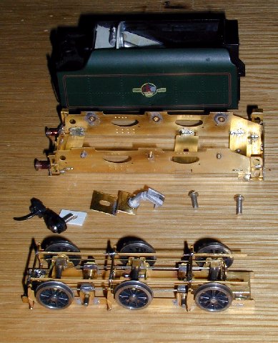
This photo show the parts for the chassis ready to assemble.
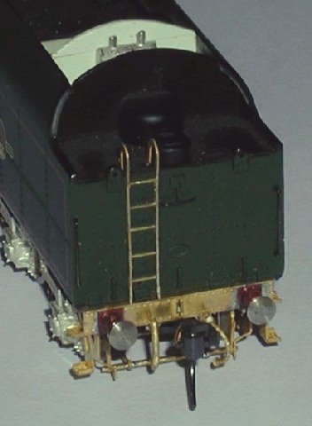
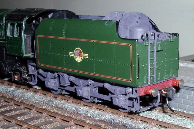
A bonus with the chassis kit is an etched ladder that makes up rather nicely and looks better than the plastic original. So far I have added a fall plate and a coal space floor to the Bachmann original, outstanding as rather noticeable is to fit cab doors.
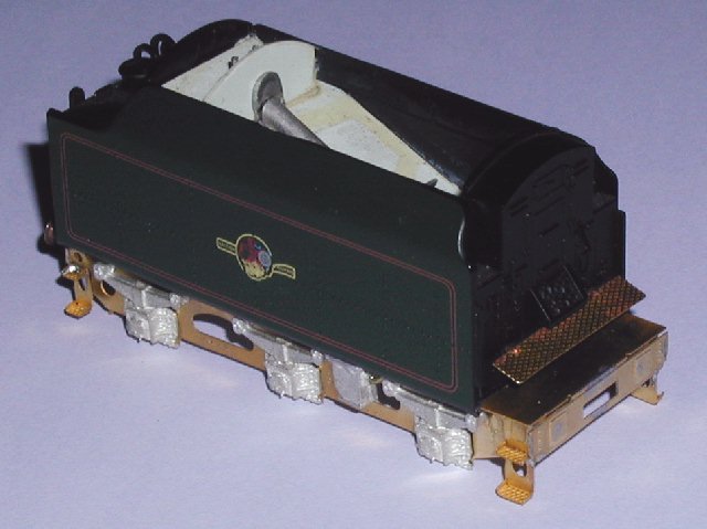
The frames are attached to a plasticard floor on the body with a single screw, two further screws hold the remaining parts, the rear screw also holds the Kadee coupler, a spacer and the water scoop. The front screw also holds the drawbar.
The subassemblies ready to screw together,
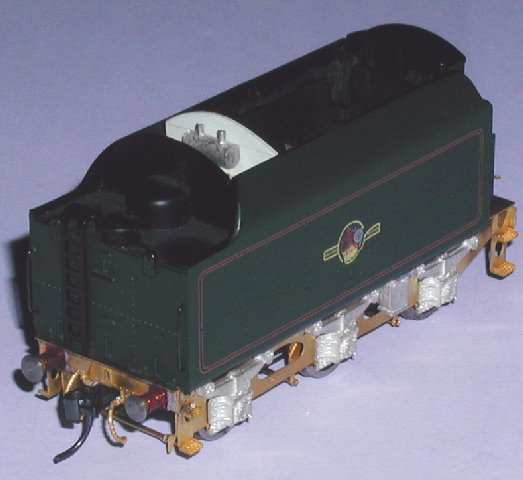
Frames assembled to body and then the chassis and wheels,
Test running in primer, front.
and rear.
Copyright Keith Norgrove.
Last revised: August 27, 2003